Amphibious unmanned aerial vehicle structure

An amphibious, unmanned aerial vehicle technology, applied in the direction of unmanned aircraft, motor vehicles, aircraft, etc., can solve the limitation of the flexibility, reliability and versatility of UAV equipment, and can not effectively solve the problem of UAV water surface Problems affecting the reliability of UAV take-off and landing operations, etc., to achieve the effect of improving flexibility and reliability, simple structure, flexible and convenient use

Active Publication Date: 2019-01-01
JINING XINRUIDA INFORMATION TECH CO LTD
View PDF5 Cites 2 Cited by
  • Summary
  • Abstract
  • Description
  • Claims
  • Application Information

AI Technical Summary

Problems solved by technology

[0002] The currently used UAV equipment often only has the ability to perform take-off and landing operations on land. Although it can basically meet the needs of use, it cannot effectively realize the needs of take-off and landing on the water, which greatly limits the ability of unmanned aerial vehicles. The flexibility, reliability and versatility of the use of man-machine equipment. In response to this problem, although some devices such as buoys have been developed on the UAV to realize the ability of the UAV to take off and land on the water surface, but it is still It only solves the common take-off and landing problem. Since the water surface, especially rivers and other water bodies, has a certain degree of fluidity, the current UAVs have poor positioning ability on the water surface after landing on the water surface, which seriously affects the UAVs on the water surface. In addition, there are often requirements for UAVs to conduct directional navigation at a certain distance on the water surface, but the current method of adding traditional landing gear to UAVs cannot effectively solve the problem of UAV surface heading. Therefore, in view of this situation, it is urgent to develop a new UAV structure to meet the needs of actual use

Method used


Image

  • Amphibious unmanned aerial vehicle structure

Examples


Embodiment Construction

[0014] In order to make the technical means, creative features, goals and effects achieved by the present invention easy to understand, the present invention will be further described below in conjunction with specific embodiments.

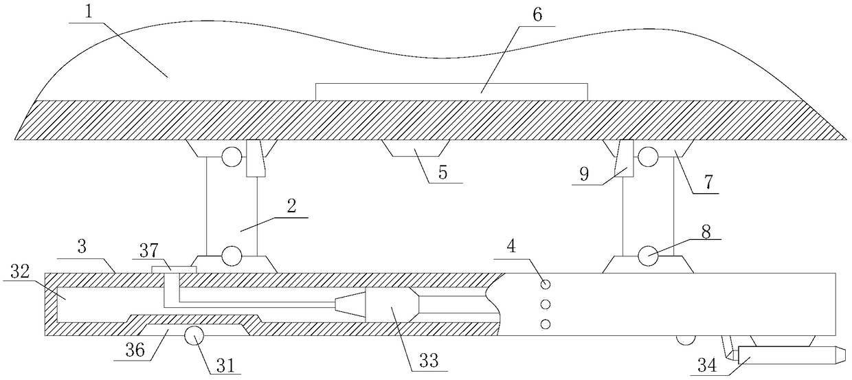
[0015] Such as figure 1 The structure of an amphibious unmanned aerial vehicle includes a fuselage 1, a bearing column 2, a landing gear 3, a liquid level sensor 4, a ranging device 5 and a landing adaptation control system 6, wherein there are at least two landing gears 3, The bearing column 2 is connected to the lower surface of the fuselage 1, the axis of the landing gear 3 and the axis of the fuselage 1 form an angle of 0°-60°, and each landing gear 3 is connected to the fuselage through at least one bearing column 2, The two ends of the bearing column 2 are respectively hinged with the fuselage 1 and the landing gear 3 through the turntable mechanism 7. The axis of the bearing column 2 intersects with the axes of the fuselage 1 and the landin...


PUM


Abstract

The invention relates to an amphibious unmanned aerial vehicle structure, which comprises a fuselage, bearing columns, at least two undercarriages, a plurality of liquid level sensors, at least two ranging devices and a falling adaptive control system, wherein the undercarriages are connected with the lower surface of the fuselage through the bearing columns; the two ends of the bearing columns are separately hinged to the fuselage and the undercarriages through rotating table mechanisms; the liquid level sensors are uniformly distributed on the outer surface of each undercarriage; the liquidlevel sensors on the same undercarriage are uniformly distributed in a straight line direction where the upper end surfaces of the undercarriages are vertically distributed; the ranging devices are uniformly distributed on the lower end surface of the fuselage in the axial direction of the fuselage; the axes of the ranging devices and a horizontal plane are vertically distributed; and each undercarriage comprises a road wheel, a buoy, a jet pump and a jet nozzle. On one hand, the requirement that unmanned aerial vehicle equipment takes off from and lands to the land and a water surface can bemet, and on the other hand, the unmanned aerial vehicle equipment has relatively high navigation capacity on the water surface.

Description

technical field [0001] The invention relates to an unmanned aerial vehicle body, specifically an amphibious unmanned aerial vehicle structure. Background technique [0002] The currently used UAV equipment often only has the ability to perform take-off and landing operations on land. Although it can basically meet the needs of use, it cannot effectively realize the needs of take-off and landing on the water, which greatly limits the ability of unmanned aerial vehicles. The flexibility, reliability and versatility of the use of man-machine equipment. In response to this problem, although some devices such as buoys have been developed on the UAV to realize the ability of the UAV to take off and land on the water surface, but it is still It only solves the common take-off and landing problem. Since the water surface, especially rivers and other water bodies, has a certain degree of fluidity, the current UAVs have poor positioning ability on the water surface after landing on th...

Claims


Application Information

Patent Timeline
Patent Type & Authority Applications(China)
IPC IPC(8): B64C25/34B64C25/54
CPCB64C25/34B64C25/54B64U70/00
Inventor 李传广
Owner JINING XINRUIDA INFORMATION TECH CO LTD
Why Eureka
Try Eureka