Slideway device for conveying heavy equipment

A technology of heavy equipment and slideway, which is applied in the direction of conveyors, mechanical conveyors, transportation and packaging, etc. It can solve the problems of high labor intensity, low safety factor, and accidental damage to heavy equipment, so as to reduce labor intensity and avoid the center of gravity Unstability, safety-enhancing effects

Pending Publication Date: 2019-01-01
海控三鑫(蚌埠)新能源材料有限公司
View PDF0 Cites 0 Cited by
  • Summary
  • Abstract
  • Description
  • Claims
  • Application Information

AI Technical Summary

Problems solved by technology

[0002] In recent years, as the level of industrialization in China and other countries has become higher and higher, the number of heavy equipment has increased. In the process of handling heavy equipment, it is often necessary to carry out short-distance equipment in a relatively closed space. At this time, neither the crane nor the locomotive can carry out the operation
In this case, the method of adding rollers to the equipment is usually used for transportation, but this method has many disadvantages: high ground flatness requirements, high labor intensity, low transportation efficiency, low safety factor, etc., especially in When there are slopes on the ground and high-altitude operations, the center of gravity of the equipment and the speed of the rollers are difficult to control, which is prone to accidental damage to heavy equipment and personal injury

Method used


Image

  • Slideway device for conveying heavy equipment
  • Slideway device for conveying heavy equipment
  • Slideway device for conveying heavy equipment

Examples


Embodiment Construction

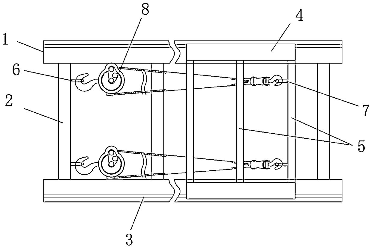
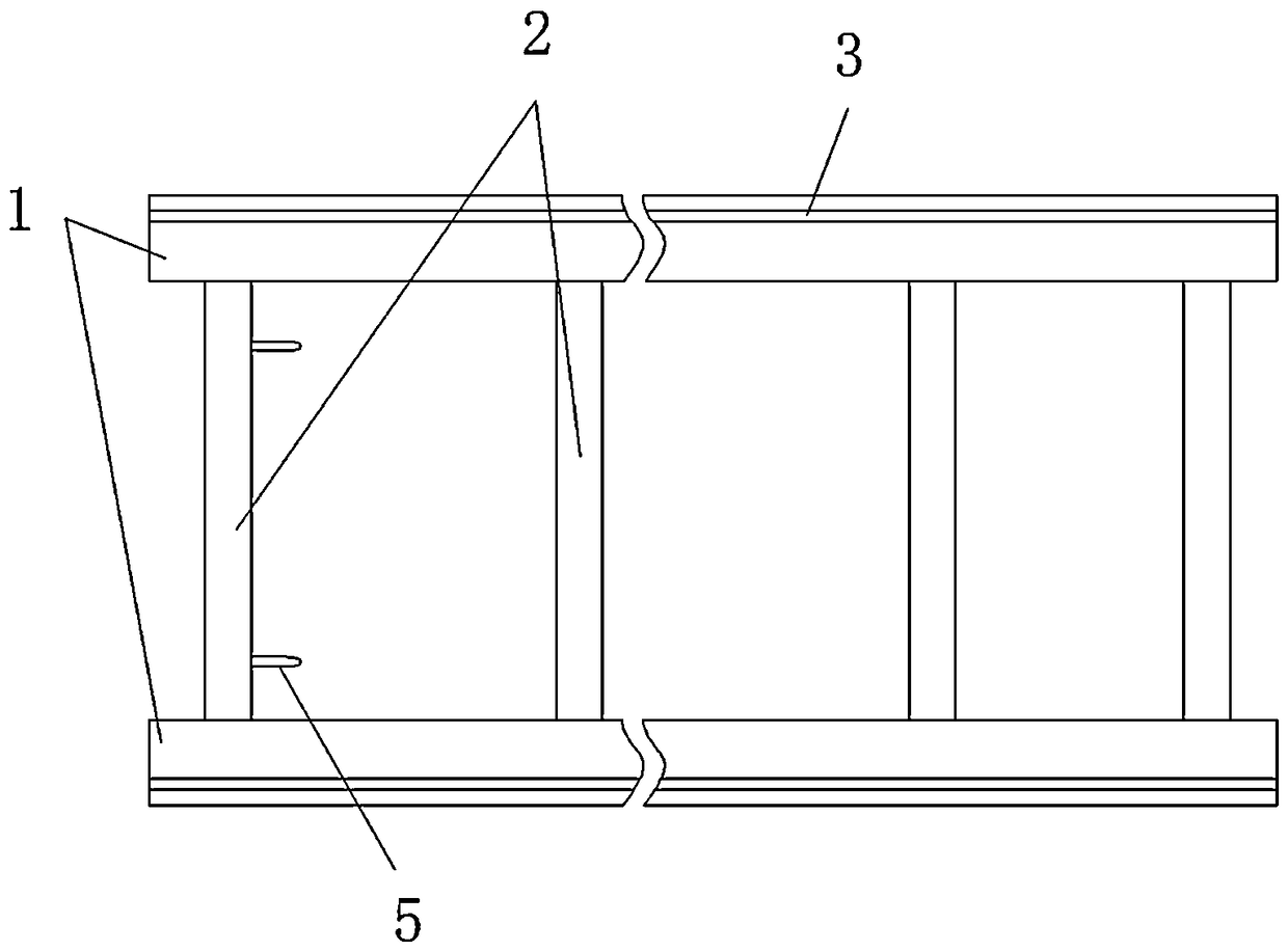
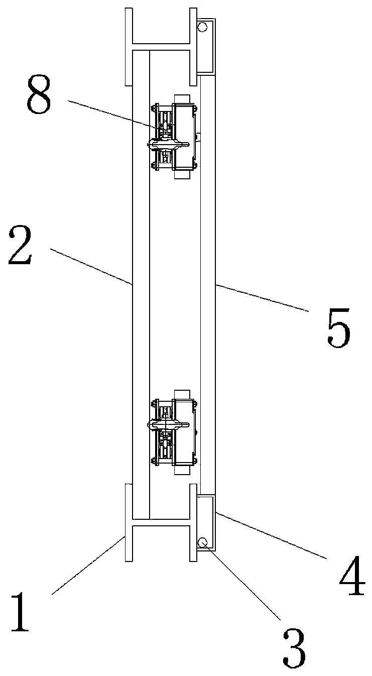
[0014] combine Figure 1~3 As shown, the present invention provides a slideway device for transporting heavy equipment, including a slideway base and a support bracket arranged on the top of the slideway base; the slideway base includes two slide rails 1 arranged in parallel and spaced apart, The slide rail 1 can be made of I-shaped steel, and the two slide rails 1 are fixedly connected by a set of longitudinal connecting rods 2. The tops of the two slide rails 1 are respectively provided with guiding ribs 3 along the axial direction; the supporting bracket includes Two crossbeams 4 arranged at intervals are fixedly connected by a group of longitudinal beams 5, and the two crossbeams 4 correspond to two slide rails 1 respectively; preferably, the slide rails 1 are 15mm wider than the crossbeam 4.

[0015] The crossbeam 4 is in the shape of "冂" with the opening downward; the opening of the crossbeam 4 cooperates with the guiding rib 3; preferably, the guiding rib 3 is located i...


PUM


Abstract

The invention discloses a slideway device for conveying heavy equipment. The slideway device comprises a slideway base and a supporting bracket arranged at the top of the slideway base; the slideway base comprises two sliding rails which are arranged at intervals in parallel, the two sliding rails are fixedly connected through a group of longitudinal connecting rods, and guide convex ribs are arranged on the tops of the two sliding rails in the axial direction; the supporting bracket comprises two cross beams which are arranged at intervals, the two cross beams are fixedly connected through agroup of longitudinal beams, the two cross beams correspond to the two sliding rails, and the cross beams are in an N shape with openings downwards; the openings of the cross beams are matched with the guide convex ribs to enable the supporting bracket and the slideway base to form sliding friction fit; and one connecting rod is provided with a first hanging ring, one longitudinal beam is providedwith a second hanging ring, the first hanging ring corresponds to the second hanging ring, and a manual hoist is connected between the first hanging ring and the second hanging ring. According to theslideway device, the equipment can be safely and stably conveyed, the structure is simple, and the labor intensity is reduced.

Description

technical field [0001] The invention relates to the technical field of mechanical tooling, in particular to a slideway device for transporting heavy equipment. Background technique [0002] In recent years, as the level of industrialization in China and other countries has become higher and higher, the number of heavy equipment has increased. In the process of handling heavy equipment, it is often necessary to carry out short-distance equipment in a relatively closed space. At this time, neither the crane nor the locomotive can carry out the operation. In this case, the method of adding rollers to the equipment is usually used for transportation, but this method has many disadvantages: high ground flatness requirements, high labor intensity, low transportation efficiency, low safety factor, etc., especially in When there are slopes on the ground and high-altitude operations, the center of gravity of the equipment and the speed of the rollers are difficult to control, which ...

Claims


Application Information

Patent Timeline
IPC IPC(8): B65G35/00
CPCB65G35/00
Inventor 谢培恒王东乔永贞张德焦祝家国李鹏王伟
Owner 海控三鑫(蚌埠)新能源材料有限公司
Why Eureka
Try Eureka