Automatic wheel changing device

An automatic and sliding technology, which is applied in the direction of transportation and packaging, conveying filamentous materials, thin material processing, etc., can solve the problems of low work efficiency, achieve the effect of improving efficiency and simple operation

Pending Publication Date: 2019-01-01
张家港市骏马钢帘线有限公司
View PDF0 Cites 1 Cited by
  • Summary
  • Abstract
  • Description
  • Claims
  • Application Information

AI Technical Summary

Problems solved by technology

[0002] During the steel cord production process, when the semi-finished steel cord is electroplated with brass, the steel cord needs to be released from the I-shaped wheel for heat treatment and electroplating, and finally an electroplated brass wire is formed. The existing automatic wheel changing device includes a frame And the two I-shaped wheels set on the frame, the steel cord between the two I-shaped wheels is wound and welded by the wire-passing wheel, when the wheel is changed, the frame needs to be rotated to facilitate the wheel change, the actual production In the middle, sometimes the manual operation of the wheel changing device is used, and the work efficiency is low

Method used


Image

  • Automatic wheel changing device
  • Automatic wheel changing device
  • Automatic wheel changing device

Examples


Embodiment Construction

[0023] The present invention will be described in detail in conjunction with accompanying drawing now. This figure is a simplified schematic diagram only illustrating the basic structure of the present invention in a schematic manner, so it only shows the components relevant to the present invention.

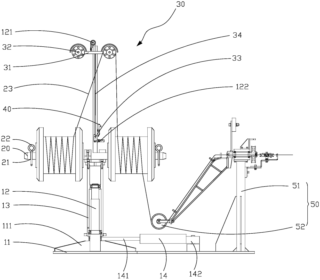
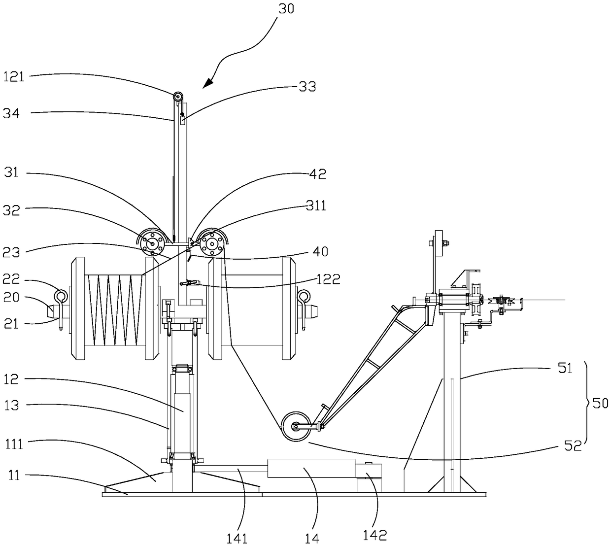
[0024] see figure 1 , the present invention provides an automatic wheel changing device, which includes a frame 10, a steering bracket 20 arranged on the frame 10, a moving wire wheel mechanism 30 and a self-locking mechanism 40, and a frame mounted on the frame The pay-off mechanism 50 on 10 sides.

[0025] The frame 10 includes a base plate 11 , a column 12 protruding from the base plate 11 , a rotating sleeve 13 rotatably sleeved on the outside of the column 12 , and a cylinder 14 that drives the rotating sleeve 13 to rotate.

[0026] A base 111 is arranged above the bottom plate 11 , the column 12 protrudes above the base 111 , and the rotating sleeve 13 is rotatably arran...


PUM


Abstract

The invention discloses an automatic wheel changing device. The automatic wheel changing device comprises a machine frame, two steering brackets arranged on the machine frame and an air cylinder driving the machine frame to rotate, wherein an I-shaped wheel is placed on each steering bracket; the machine frame comprises a bottom plate arranged at the bottom; a convex block is arranged at the bottom of the machine frame in an outward convex mode; one end of the air cylinder is an extension bar; the end, far away from the extension bar, of the air cylinder is hinged to the bottom plate; and theextension bar is hinged to the convex block. According to the automatic wheel changing device, the two ends of the air cylinder are correspondingly hinged to the bottom plate and a rotating sleeve, when a counterweight block is far away from a limiting switch, the air cylinder is controlled to drive the rotating sleeve to rotate, so that the automatic direction changing of the two I-shaped wheelsis realized, the operation is simple, and the efficiency is improved.

Description

technical field [0001] The invention relates to the field of automatic wheel changing devices, in particular, to an automatic wheel changing device. Background technique [0002] During the steel cord production process, when the semi-finished steel cord is electroplated with brass, the steel cord needs to be released from the I-shaped wheel for heat treatment and electroplating, and finally an electroplated brass wire is formed. The existing automatic wheel changing device includes a frame And the two I-shaped wheels set on the frame, the steel cord between the two I-shaped wheels is wound and welded by the wire passing wheel. When changing the wheels, the frame needs to be rotated to facilitate the wheel change. The actual production In the process, manual operation of the wheel changing device is sometimes used, and the work efficiency is low. Contents of the invention [0003] The technical problem to be solved by the present invention is: in order to overcome the abo...

Claims


Application Information

Patent Timeline
Patent Type & Authority Applications(China)
IPC IPC(8): B65H49/32B65H67/02B65H57/14
CPCB65H49/324B65H57/14B65H67/02B65H2701/36
Inventor 罗亚平姜峰
Owner 张家港市骏马钢帘线有限公司
Why Eureka
Try Eureka