Lithium battery carrying structure suitable for stacking machine

A technology of stacker and lithium battery, which is applied in the field of lithium battery handling structure, can solve the problems of inconvenient control and maintenance, unstable clamp picking and placing, heavy clamp weight, etc., and achieves the reduction of labor intensity, convenient control and maintenance, and low cost. low effect

Pending Publication Date: 2022-02-15
深圳力生物流仓储科技有限公司
View PDF0 Cites 1 Cited by
  • Summary
  • Abstract
  • Description
  • Claims
  • Application Information

AI Technical Summary

Problems solved by technology

At present, the existing technology is mainly divided into two methods for the handling of lithium batteries outside the drying furnace and the operation of sending lithium batteries into the drying furnace: one is manually picked and placed, and the other is automatically picked and placed by manipulators; and Many lithium battery manufacturers mostly use manipulators for handling. The specific operation is to place multiple lithium batteries on the jig through the manipulator, and then send the jig into the drying furnace for drying. When removing the jig, the grabbing position can only be located at one end of the jig, and the jig fully loaded with lithium batteries is very heavy. Therefore, whether it is grabbed manually or by a robot, the grabbing point is not located at the center of gravity, and the jig is not stable when it is picked and placed. The problem is that it is easy to cause the accident of the fixture falling, and the manual grabbing is labor-intensive, costly, and low-efficiency, while the automatic grabbing of the manipulator still has the defect of inconvenient control and maintenance, and it must meet the compatibility of batteries with different sizes. , the cost is also high

Method used


Image

  • Lithium battery carrying structure suitable for stacking machine
  • Lithium battery carrying structure suitable for stacking machine
  • Lithium battery carrying structure suitable for stacking machine

Examples


Embodiment Construction

[0036] The present invention will be further described in detail below in conjunction with the accompanying drawings and embodiments. It should be understood that the specific embodiments described here are only used to explain the present invention, but not to limit the present invention. In addition, it should be noted that, for the convenience of description, only some structures related to the present invention are shown in the drawings but not all structures.

[0037] In the description of the present invention, unless otherwise clearly specified and limited, the terms "connected", "connected" and "fixed" should be understood in a broad sense, for example, it can be a fixed connection, a detachable connection, or an integrated ; It can be a mechanical connection or an electrical connection; it can be a direct connection or an indirect connection through an intermediary, and it can be the internal communication of two components or the interaction relationship between two ...


PUM


Abstract

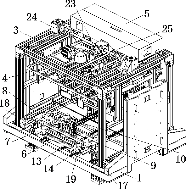
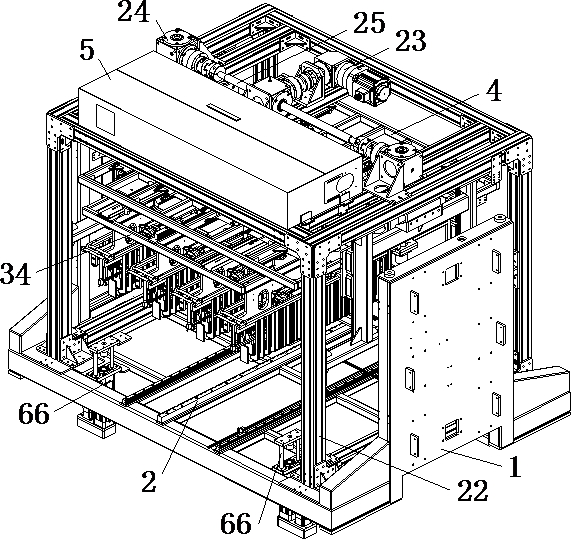
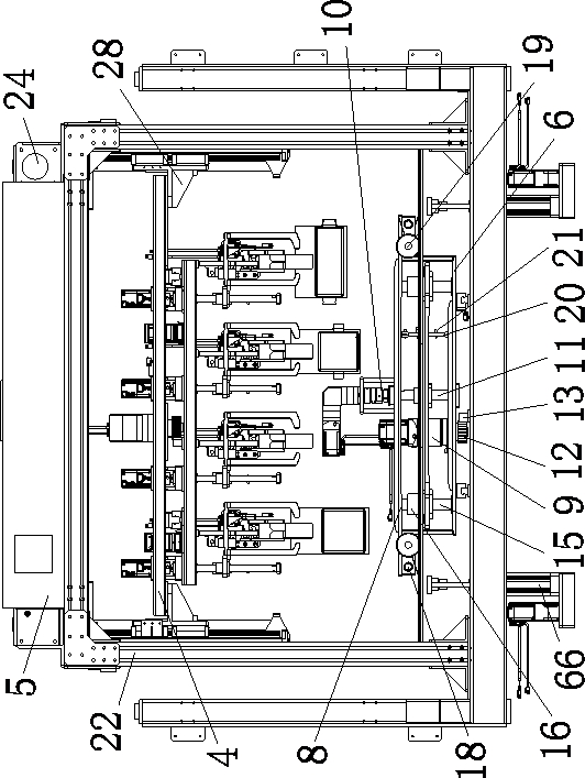
The invention discloses a lithium battery carrying structure suitable for a stacking machine. The invention comprises a base arranged on a stacking machine, a tray taking mechanism arranged on the base, a lifting mechanism arranged above the tray taking mechanism and arranged on the base, a battery carrying mechanism arranged above the tray taking mechanism and connected to the lower portion of the lifting mechanism, a battery conveying mechanism arranged on the top of the lifting mechanism and connected with the tray taking mechanism and the tray taking mechanism, and an electric cabinet electrically connected with the lifting mechanism and the battery carrying mechanism. during working, the stacking machine drives the base to move, the tray taking mechanism takes or sends back the feeding tray or the battery tray or the battery clamp and drives the feeding tray or the battery tray or the battery clamp to move, and the battery carrying mechanism clamps and carries lithium batteries under the cooperation of the tray taking mechanism and the lifting mechanism. Automatic carrying of lithium batteries is achieved, the carrying mode of manual grabbing and mechanical arm grabbing is replaced, taking and placing are more stable, falling accidents are not likely to happen, efficiency is high, compatibility is high, and control and maintenance are more convenient.

Description

technical field [0001] The invention relates to the technical field of lithium battery production, in particular to a lithium battery handling structure suitable for a stacker. Background technique [0002] Before the lithium battery is injected, there is a process that needs to send the lithium battery to a drying oven for drying, so as to prevent moisture from mixing into the battery and affecting the performance of the lithium battery. At present, the existing technology is mainly divided into two methods for the handling of lithium batteries outside the drying furnace and the operation of sending lithium batteries into the drying furnace: one is manually picked and placed, and the other is automatically picked and placed by manipulators; and Many lithium battery manufacturers mostly use manipulators for handling. The specific operation is to place multiple lithium batteries on the jig through the manipulator, and then send the jig into the drying furnace for drying. Whe...

Claims


Application Information

Patent Timeline
Patent Type & Authority Applications(China)
IPC IPC(8): B65G61/00B65G47/92B65G43/10H01M6/14H01M10/058
CPCB65G61/00B65G47/92B65G43/10H01M10/058H01M6/14Y02E60/10Y02P70/50
Inventor 李国华黄代理罗永明
Owner 深圳力生物流仓储科技有限公司
Why Eureka
Try Eureka