Mechanical automatic reversing valve and using method thereof

An automatic reversing and reversing valve technology, applied in mechanical equipment, multi-port valves, control valves, etc., can solve the problems of high failure rate, troublesome power supply, troublesome second wiring, etc., to achieve low failure rate and easy use. , the effect of simple structure

Pending Publication Date: 2021-12-21
张辉
View PDF1 Cites 2 Cited by
  • Summary
  • Abstract
  • Description
  • Claims
  • Application Information

AI Technical Summary

Problems solved by technology

[0002] It is known that a reversing valve is usually required to control the telescopic operation of the hydraulic cylinder. At present, the reversing valve is divided into an electromagnetic reversing valve and a manual reversing valve; the electromagnetic reversing valve needs to use a power supply, but the power supply is troublesome when working in the field. The weight of the first battery pack is increased, and the second wiring is also more troublesome. The electromagnetic reversing valve cannot be used on site, and only a manual reversing valve can be used, resulting in increased manual workload and difficult operation, and low operating efficiency; In addition, the electromagnetic reversing valve The directional valve needs to be used in conjunction with the electric induction switch to meet the work requirements, and various relays need to be added, resulting in a high failure rate. This phenomenon is an urgent problem to be solved by those skilled in the art;
[0003] Chinese patent (publication number: CN209354694U) discloses a fluid automatic control reversing device. The cover is sealed and connected to both ends of the valve body; the adjustment rod is connected to both ends of the valve core, one on the left and one on the left, and the upper end surface of the side cover of the valve body is provided with a controller oil port, an external control oil port X, and an external drain port Y They are respectively located on both sides of oil ports P, T, A, and B, and communicate with the controller oil port on the side cover; the adjustment rod controls the stroke of the spool, and the relative position of the spool and the oil groove controls the flow direction and direction of the oil. The flow rate requires the oil pressure of external control oil port X and external oil drain port Y to make the controller reversing to achieve the purpose of actuator reversing. The structure is complex and the failure rate is high.

Method used


Image

  • Mechanical automatic reversing valve and using method thereof
  • Mechanical automatic reversing valve and using method thereof
  • Mechanical automatic reversing valve and using method thereof

Examples


Embodiment 1

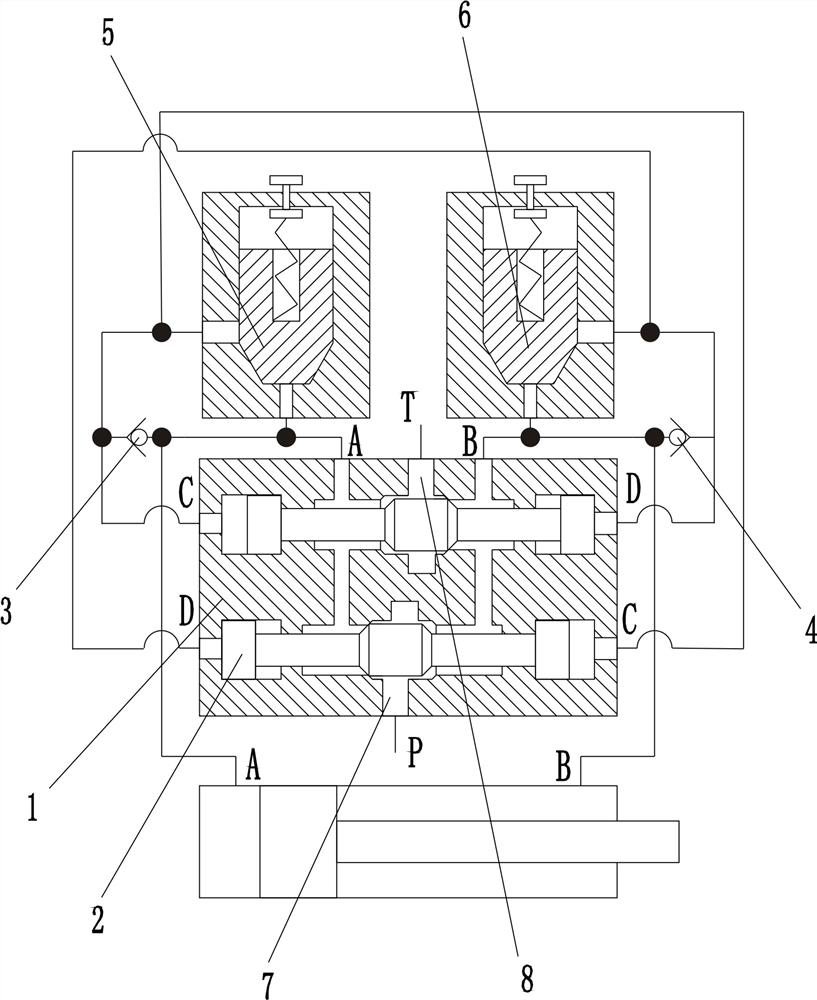
[0027] Join figure 1 An automatic mechanical valve for automatic control of the running direction of the actuator, comprising a valve body 1, valve core 2, I3 check valve, the check valve Ⅱ4, pressure regulating valve and a pressure regulating valve Ⅰ5 Ⅱ 6; the valve body 1 is provided with a hydraulic oil supply port for high-pressure oil system corresponding to communication pipe P7, corresponding to the tank in communication with the hydraulic system oil return port T8, and a piston chamber corresponding to the actuator connection port communicating A9, and performing means corresponding to the other piston chamber communicating connection port B10;

[0028] The valve body 1 equipped with the valve body cavity, the cavity is attached to the valve body for switching the connection port the A9, B10 connecting port and the oil port P7, the correspondence between the valve core return port communicating relationship T8 2; valve 1 A9 equipped with the connection port corresponding t...

Embodiment 2

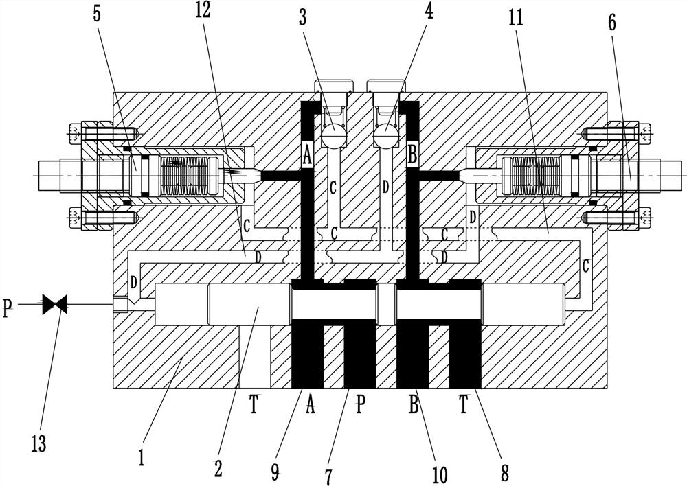
[0031] Join Figure 2 ~ 3, Mechanical automatic valve of the embodiment of the present embodiment is a further embodiment of the embodiment defining, with the first embodiment except that: the cavity is a valve body, valve stem and valve body 2 comprises a core step, the middle and both ends of the valve stem and the valve chamber is provided with a sealing sliding fit in the valve body corresponding to the step, are sequentially laid side by side in one side of the valve body cavity there is the return port T8, the A9 connection port, an oil supply port P7, and a return port connected to port T8 B10; B10 and the connecting port T8 corresponding to the return port when the connection port communicates with the oil supply port P7 communicates A9, A9 when the connection port corresponding to the return port T8 communicates with the oil supply port connection port B10 P7 communicates, simple structure easy to assemble;

[0032] The machine according to the present embodiment of the au...

Embodiment 3

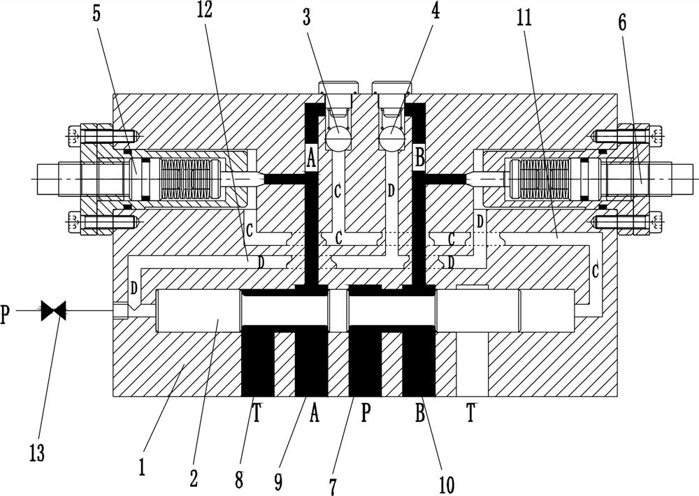
[0034] Join Figure 4 ~ 5 , Mechanical automatic valve of the embodiment of the present embodiment is a further embodiment of the embodiment defining, with the first embodiment except that: the valve body cavity is a two, respectively, the valve body and the valve chamber cavity Ⅰ ⅱ, the spool left end chamber passage ⅰ and D12 corresponding to an end of communication, and the right end corresponding to the communication passage C11, the left end of the spool chamber ⅱ communication passage C11 corresponding to an end, the right end corresponding to an end of the oil passage communicating D12; spool bore ⅰ and the valve spool bore has ⅱ core 2, the core 2 comprises a ball valve, and the valve stem step, the stem ends of the valve body and the valve body has a sealing sliding fit in a corresponding cavity step, the central stem is provided with a ball head corresponding to a respective spool chamber ⅰ valve core has a diameter greater than the diameter of the ball head between the l...


PUM


Abstract

The invention relates to a mechanical automatic reversing valve and a using method thereof, and belongs to the technical field of reversing valves. The mechanical automatic reversing valve is used for automatically controlling the running direction of an executing mechanism and comprises a valve body, a reversing valve element, a one-way valve I, a one-way valve II, a pressure regulating valve I and a pressure regulating valve II. The valve body is provided with an oil supply port P correspondingly communicated with a high-pressure oil supply pipe of a hydraulic system, an oil return port T correspondingly communicated with an oil tank of the hydraulic system, a connecting port A correspondingly communicated with one piston cavity of the executing mechanism and a connecting port B correspondingly communicated with the other piston cavity of the executing mechanism; a valve element cavity is formed in the valve body, and the reversing valve element used for switching the corresponding communication relation between the connecting port A and the connecting port B and between the oil supply port P and the oil return port T is installed in the valve element cavity. The valve body is internally provided with an oil path C which enables the connecting port A to be correspondingly communicated with one end of the valve element cavity. According to the mechanical automatic reversing valve and the using method thereof, the structure is simple, the failure rate is low, the purpose of automatic reversing of the reversing valve element can be achieved, and therefore the executing mechanism can be controlled to do automatic reciprocating motion.

Description

Technical field [0001] Technical Field The present invention relates to a valve, particularly to a machine and method of using the automatic valve. Background technique [0002] Known, generally require operation of the telescopic cylinder valve control, the current into the solenoid valve and the manual valve valve; solenoid valve requires the use of power supply, but the power supply field operations troublesome, increase the weight of the first battery, the second wiring is relatively cumbersome, the scene can not use electromagnetic valve, the valve can only manually, resulting in increased labor work and the operation is also difficult to grasp, low operating efficiency; In addition, electromagnetic transducer the valve needs and with the use of electric induction switch in order to meet the job requirements, the need to increase various relays, leading to a high failure rate, this phenomenon is skilled in the art problems to be solved; [0003] China Patent (Publication No....

Claims


Application Information

Patent Timeline
Patent Type & Authority Applications(China)
IPC IPC(8): F15B13/04F16K11/07F16K15/18B66F3/25B21D28/24B21D22/20
CPCF15B13/0402F15B13/0401F16K11/07F16K15/18B66F3/25B21D28/24B21D22/20
Inventor 张辉
Owner 张辉
Why Eureka
Try Eureka