Downhole gas slow-release device

A slow-release device and gas technology, which is applied in the field of automatic control of oil well casing gas pressure release, can solve the problems of unfavorable stable production of oil wells, inconvenient production management, and sand production in formations, so as to avoid excessive drop of bottom-hole flow pressure and ensure Normal production and elimination of the effect of fluid level drop

Inactive Publication Date: 2019-01-01
SHAANXI XINGCHEN PETROLEUM TECH
View PDF0 Cites 1 Cited by
  • Summary
  • Abstract
  • Description
  • Claims
  • Application Information

AI Technical Summary

Problems solved by technology

In this way, casing gas is wasted, air pollution is caused, and it is not conducive to the stable production of oil wells, resulting in sand production in the formation
Therefore, the problem of excessive casing pressure in oil wells brings a lot of inconvenience to production management

Method used


Image

  • Downhole gas slow-release device

Examples


Embodiment Construction

[0011] The present invention will be described in detail below in conjunction with the accompanying drawings.

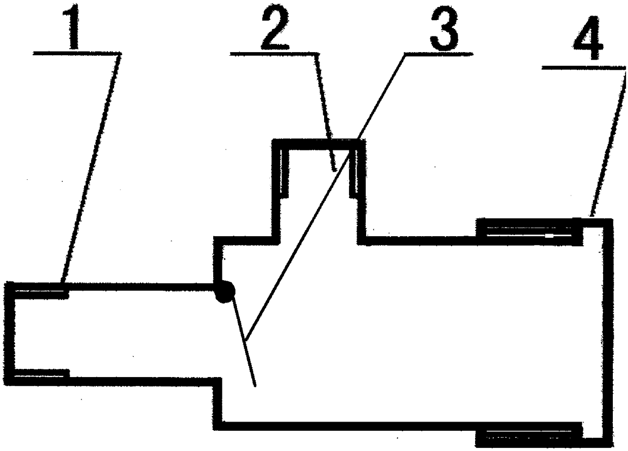
[0012] Such as figure 1 As shown, the present invention provides a downhole gas slow release device, comprising: a housing 4, an inlet 1 and an outlet 2 are arranged on the housing 4, a baffle 3 is arranged at the inlet 1, and the baffle 3 passes through The hinge is installed on the inner wall of the inlet, and the baffle plate 3 matches the inlet 1. The inlet 1 and the outlet 2 are arranged vertically, and the edge of the baffle plate 3 is provided with a sealing strip.

[0013] Working principle: The casing gas enters the downhole gas slow release device from the inlet. When the pressure is lower than the yield stress of the spring, the baffle is tightly pressed against the inner port of the casing gas inlet, and the casing gas cannot be released and is temporarily collected in the casing. The valve The body is in the closed state; when the casing gas pressure c...


PUM


Abstract

The invention discloses a downhole gas slow-release device which comprises a shell. An inlet and an outlet are formed in the shell, a baffle is arranged at the inlet and mounted on the inner wall of the inlet through hinges, and the baffle is matched with the inlet. The situations that the oil well sleeve pressure is excessively high, consequently the dynamic liquid surface is dropped, the pump efficiency is lowered, and oil well production is abnormal are eliminated, dynamic control over the oil well sleeve pressure is achieved, and normal production of an oil well is guaranteed. The situation that sleeve gas is manually released, consequently drop of the downhole flow pressure is excessively fast, the formation instantaneous production pressure difference is excessively large, an oil well sand prevention process is damaged, and consequently the well lying phenomenon is caused by formation excited sand discharging are avoided, the oil well exemption period is prolonged, and the crudeoil yield is increased.

Description

technical field [0001] The utility model relates to the automatic control technology of oil well casing gas pressure release, in particular to a downhole gas slow release device. Background technique [0002] In the production process of pumping wells in oil fields, the average submerged pressure of deep well pumps is generally 4.4MPa, which is 10MPa lower than the saturation pressure. Therefore, a large amount of dissolved gas in crude oil has been precipitated at the suction port of the pump, and enters the working cylinder of the deep well pump together with the oil and water, resulting in a decrease in pump efficiency. Especially for wells with a large amount of dissolved gas, part of the dissolved gas can be pumped to the surface along with the oil and water, while the other part is precipitated and accumulated in the casing, causing the casing pressure to rise and the dynamic fluid level to drop. When the liquid level drops to the suction port of the pump, the gas inv...

Claims


Application Information

Patent Timeline
Patent Type & Authority Applications(China)
IPC IPC(8): E21B34/08
CPCE21B34/08
Inventor 程世英
Owner SHAANXI XINGCHEN PETROLEUM TECH
Why Eureka
Try Eureka