Method for producing liquefied natural gas

A technology for liquefied natural gas and products, which is applied in the direction of refrigeration and liquefaction, gas fuel, and irreversible cycle compressors, etc. It can solve the problems of complex structure of pre-cooling compressors, complex structures of propane compressors, and difficult implementation of domestic equipment, etc., to achieve The effect of simple structure, simple design and manufacture, and reduced equipment

Inactive Publication Date: 2011-07-06
TECHNICAL INST OF PHYSICS & CHEMISTRY - CHINESE ACAD OF SCI
View PDF7 Cites 18 Cited by
  • Summary
  • Abstract
  • Description
  • Claims
  • Application Information

AI Technical Summary

Problems solved by technology

The mixed working medium refrigeration cycle mainly has the following types: First, the propane precooling plus mixed working medium refrigeration cycle of APCI Company, that is, the PPMR cycle. The precooling process is based on the cooling capacity provided by propane under different evaporation pressures. There are many application examples in the construction of plants and stations, which occupy a very important position. However, due to the fact that propane evaporates and exchanges heat under different pressures to provide cooling capacity, the entire system is relatively cumbersome, and the structure of the propane compressor is also complicated. Compressors have very high requirements; one is the PRICO process invented by BV Company, which is a single-stage mixed refrigeration process. The refrigerant only needs to be compressed by a single compressor, and a single throttle valve is used to throttle the refrigeration. It has less equipment and is easy t

Method used


Image

  • Method for producing liquefied natural gas
  • Method for producing liquefied natural gas
  • Method for producing liquefied natural gas

Examples


Embodiment 1

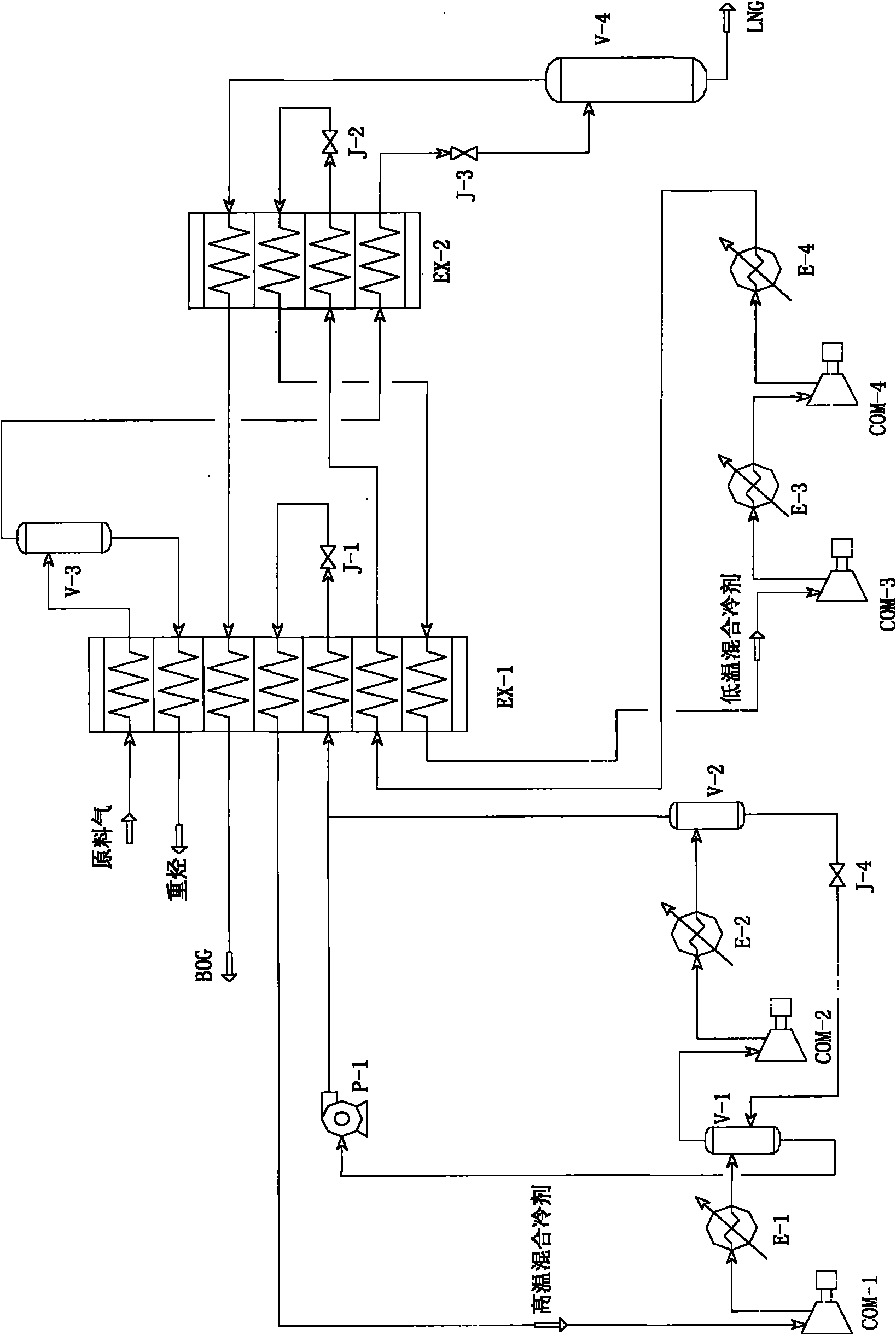
[0041] like figure 1 As shown, the raw material gas with a pressure of 4.0Mpa after purification enters the first heat exchanger EX-1 (also known as the first-stage plate-fin heat exchanger or precooler), and is cooled with other cold fluids in the first heat exchanger. After heat exchange, the temperature is cooled to about -50°C, and it exits the first heat exchanger and enters the heavy hydrocarbon separator V-3. The temperature entering the heavy hydrocarbon separator is related to the pressure of the raw gas. The higher the pressure of the raw gas, the easier it is for the heavy components in the raw gas to be liquefied; the lower the pressure, the lower the temperature required for the liquefaction of the heavy components. Therefore, the temperature entering the heavy hydrocarbon separator can be adjusted according to the feed gas pressure, but it should not be too low. In principle, the lower the temperature, the more heavy components will be liquefied, and the smaller...

Embodiment 2

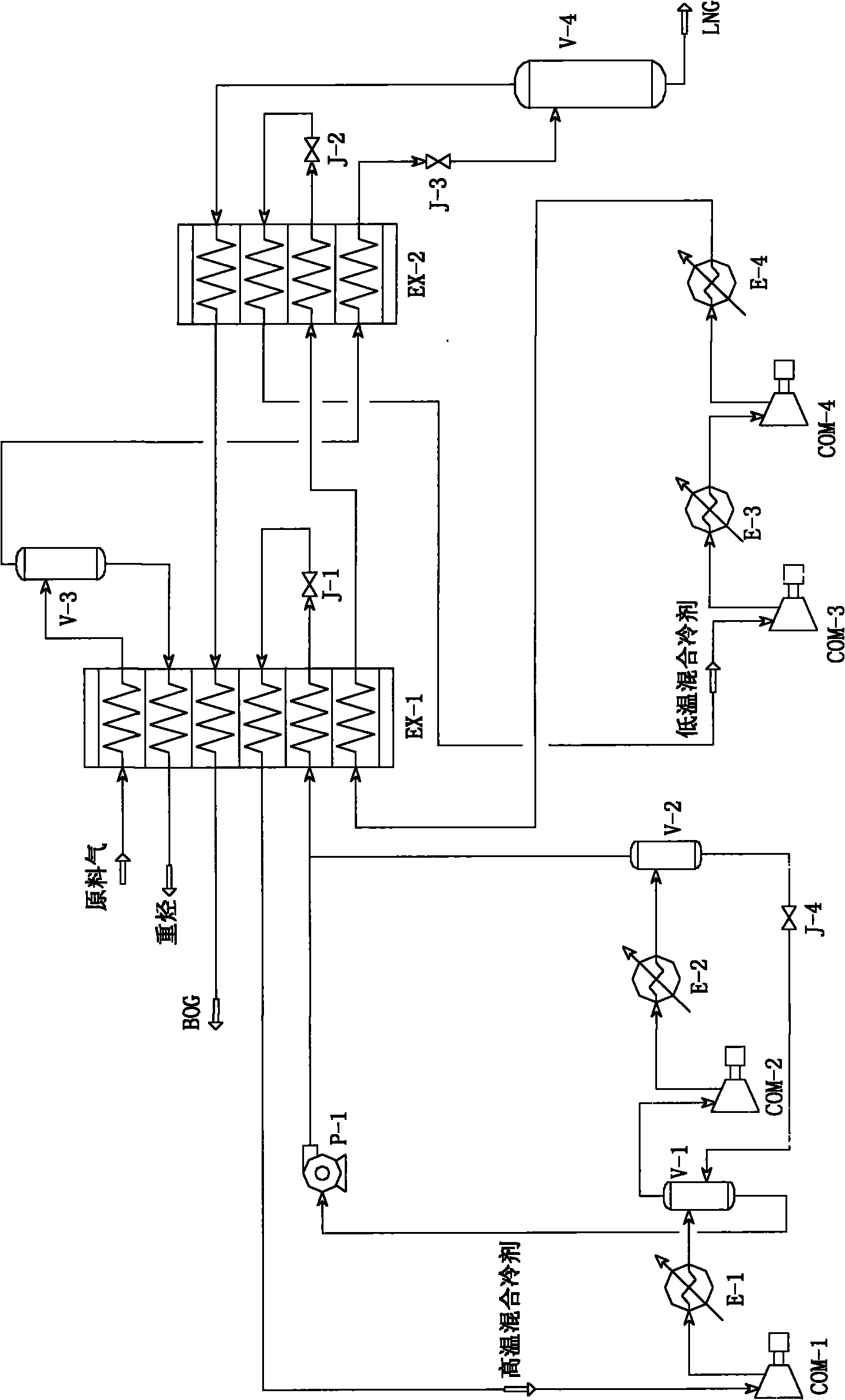
[0052] like figure 2 As shown, the difference between Embodiment 2 and Embodiment 1 is that the low-temperature mixed refrigerant enters the cold end of the second heat exchanger EX-2 through the second throttle valve J-2 to depressurize and throttling, and from the second heat exchange After the hot end of the heat exchanger EX-2 comes out, it does not enter the cold end of the first heat exchanger EX-1 as in Embodiment 1, but directly returns to the inlet of the first compressor COM-1 for compression.

[0053] Since the mixed refrigerant coming out from the hot end of the second heat exchanger EX-2 is a low-temperature fluid, generally -40°C to -70°C, the low-temperature mixed refrigerant compressor in embodiment 2 must use a low-temperature compressor; and the implementation The low-temperature mixed refrigerant compressor of Example 1 can be a normal-temperature compressor.

Embodiment 3

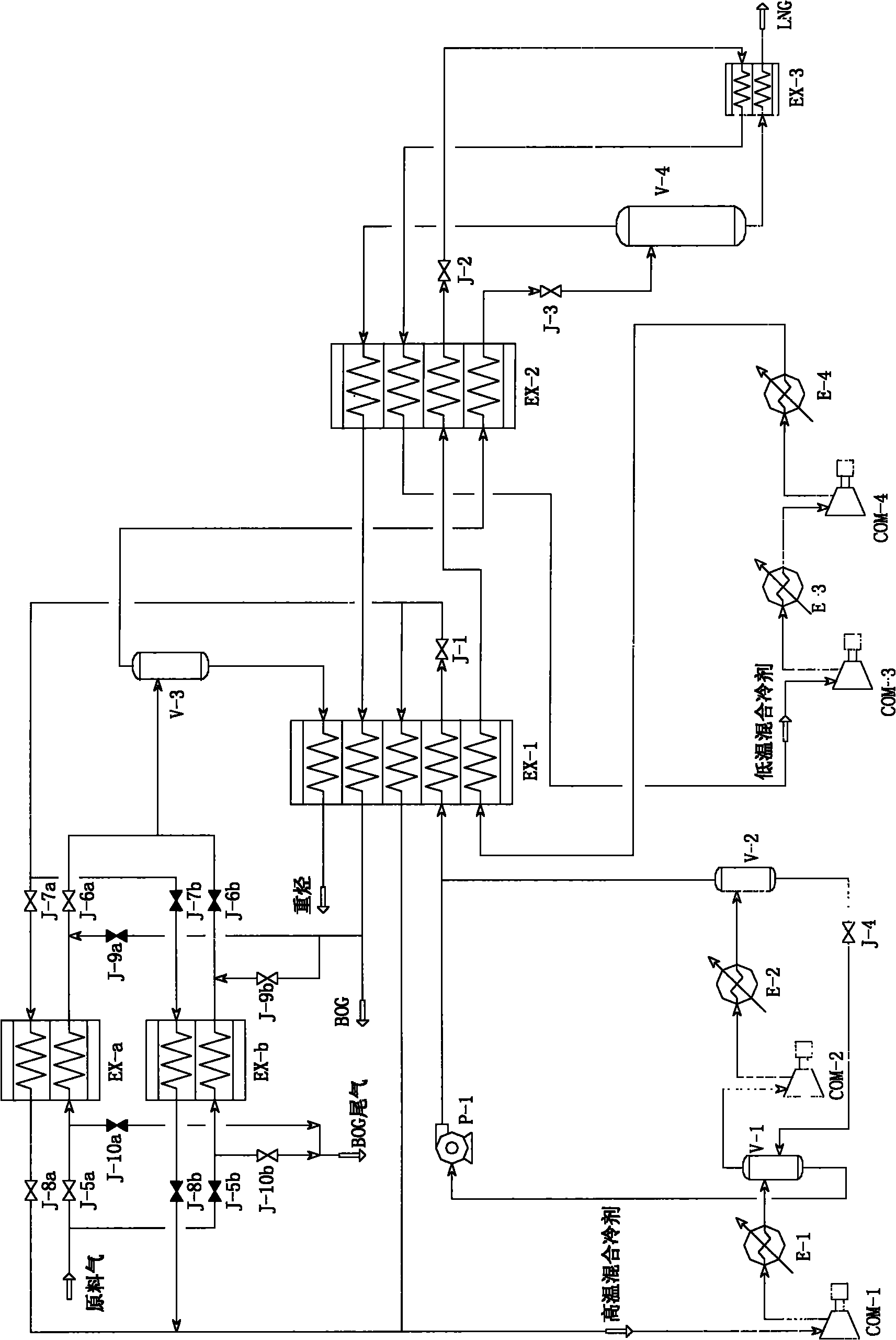
[0055] like image 3 As shown, the difference between embodiment 3 and embodiment 2 is that the switch heat exchangers EX-a and EX-b are adopted, and the subcooler EX-3 is adopted.

[0056] The purified raw material gas is selected to enter the switchable heat exchanger EX-a or EX-b through the opening and closing of switching valves J-5a and J-5b. In Example 3, take the switchable heat exchanger EX-a selected as an example (the valve J-5b is blacked out to indicate the closed state, and other blackened valves are also the same), the raw material gas exchanges heat with the cold fluid, the temperature drops, and then enters Heavy hydrocarbon separator. The cold fluid comes from the high-temperature mixed refrigerant, which is decompressed by the first throttle valve J-1, and is divided into two paths, one path provides cooling capacity for the switchable heat exchanger EX-a or EX-b, and the other path is the first heat exchanger EX-1 provides cooling capacity. The two high-...


PUM


Abstract

The invention provides a process for producing liquefied natural gas, which comprises the following steps of: introducing purified feed gas into a first heat exchanger for precooling; introducing the precooled feed gas into a heavy hydrocarbon separator for gas-liquid separation; introducing the separated gaseous fluid into a second heat exchanger, and liquefying to obtain liquid-state fluid; and depressurizing and throttling to obtain the liquefied natural gas, wherein a refrigeration cycle consists of two independent mixed working medium refrigeration cycles in a high temperature area and a low temperature area; the feed gas can pass through a reversing heat exchanger to enter the first heat exchanger; and the separated heavy hydrocarbons and BOG return to the heat exchanger for reheating. In the process, the energy consumption is low; each mixed working medium refrigeration cycle is controlled by only one throttle valve in a cold box, and the operation is simpler; due to the reversing heat exchanger, the production process is more stable and safe; and the cold quantity of the separated heavy hydrocarbons and BOG is fully recycled and discharged out of the cold box, and the energy consumption is reduced.

Description

technical field [0001] The invention relates to a method for producing liquefied natural gas, in particular to a method for producing liquefied natural gas by using natural gas, coal bed methane or other methane-rich gas as raw materials. Background technique [0002] Liquefied natural gas (LNG) refers to a low-temperature liquid mixture formed by liquefying raw material gas (natural gas, coalbed methane or other methane-rich gas) through pretreatment, purification and removal of impurities, and is liquefied by low-temperature cryogenic methods. It is a clean and efficient energy source. After the combustion of natural gas, the emission of sulfur dioxide and dust is reduced by nearly 100%, the carbon dioxide and nitrogen oxides produced are only 50% and 20% of coal, and the pollution is 1 / 4 of liquefied petroleum gas and 1 / 800 of coal. After natural gas is liquefied, its volume is reduced by about 600 times, which can greatly save storage and transportation space and cost, a...

Claims


Application Information

Patent Timeline
IPC IPC(8): C10L3/10F25B1/00
Inventor 任小坤张武史红兵
Owner TECHNICAL INST OF PHYSICS & CHEMISTRY - CHINESE ACAD OF SCI
Why Eureka
Try Eureka