Variable-load tool

A technology of variable load and tooling, applied in the direction of fluid pressure actuator, servo motor, servo meter circuit, etc., can solve the problems of long running-in time and poor running-in effect, and achieve the effect of improving the running-in effect and shortening the running-in time.

Active Publication Date: 2019-01-01
WUHAN MARINE MACHINERY PLANT
View PDF11 Cites 2 Cited by
  • Summary
  • Abstract
  • Description
  • Claims
  • Application Information

AI Technical Summary

Problems solved by technology

[0004] Since the gearbox is actually working, in addition to the input shaft having power input, the output shaft also has a load, and during the running-in, the output shaft is in an unloaded state, which makes the working conditions of the gearbox during the running-in and the actual use of the gearbox The working conditions are different, resulting in poor running-in effect and long running-in time

Method used


Image

  • Variable-load tool
  • Variable-load tool

Examples


Embodiment Construction

[0020] In order to make the object, technical solution and advantages of the present invention clearer, the implementation manner of the present invention will be further described in detail below in conjunction with the accompanying drawings.

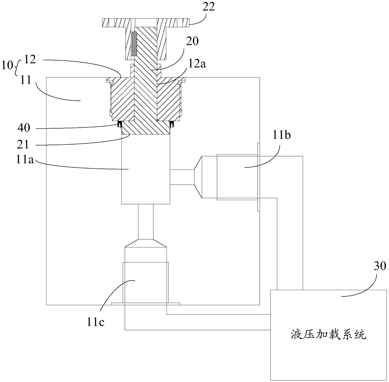
[0021] figure 1 It is a structural diagram of a variable load tooling provided by the embodiment of the present invention, as shown in figure 1 As shown, the variable load tooling includes a pressure bearing block 10 , a pressure shaft 20 and a hydraulic loading system 30 .

[0022] A columnar pressure chamber 11a is disposed inside the pressure block 10 . The bearing block 10 is further provided with a shaft hole 12a, an oil inlet hole 11b, and an oil outlet hole 11c. The shaft hole 12 a , the oil inlet hole 11 b and the oil outlet hole 11 c all communicate with the pressure chamber 11 a and the outer surface of the pressure bearing block 10 .

[0023] Wherein, the shaft hole 12a is located at one end of the pressure chamber 11a, a...


PUM


Abstract

The invention discloses a variable-load tool, and belongs to the field of test devices. The variable-load tool comprises a pressure bearing block, a pressure shaft and a hydraulic loading system, wherein a cylindrical pressure cavity is arranged in the pressure bearing block; an axle hole, an oil inlet hole and an oil outlet hole are further formed in the pressure bearing block; the axle hole is positioned in one end of the pressure cavity; the pressure shaft is inserted into the axle hole; the first end of the pressure shaft is equipped with a shaft coupler; the second end of the pressure shaft is equipped with an outer flange; the oil inlet and the axle hole are separately formed in reverse two sides of the outer flange; the oil inlet and the oil outlet are positioned at the same side ofthe outer flange; and after the pressure cavity is pressurized, the outer flange can press onto the inner wall of the pressure cavity. During running-in, the pressure shaft can be connected with theoutput shaft of to-be-run equipment through the shaft coupler, and friction force between the outer flange and the inner wall of the pressure cavity is equal to load which acts on the output shaft ofthe to-be-run equipment, so that a working condition during running-in is the same with the working condition in practical use, and therefore, the running-in effect is improved, and running-in time isshortened.

Description

technical field [0001] The invention relates to the field of testing devices, in particular to a variable load tooling. Background technique [0002] In industrial production, a lot of equipment needs to be run-in after the production is completed and before the official use, so that the equipment will be more stable when it is officially used. [0003] Take the gearbox as an example. After the production is completed, the input shaft of the gearbox is usually driven by a motor or other power to make the gears in the gearbox rotate and run in. [0004] Since the gearbox is actually working, in addition to the input shaft having power input, the output shaft also has a load, and during the running-in, the output shaft is in an unloaded state, which makes the working conditions of the gearbox during the running-in and the actual use of the gearbox The working conditions are different, resulting in poor running-in effect and long running-in time. Contents of the invention ...

Claims


Application Information

Patent Timeline
Patent Type & Authority Applications(China)
IPC IPC(8): F15B11/00F15B13/02F15B21/04
CPCF15B11/00F15B13/02F15B21/041F15B2211/205F15B2211/615
Inventor 刘帅李克飞许东邹海龙万松罗杰
Owner WUHAN MARINE MACHINERY PLANT
Why Eureka
Try Eureka