Graded damping vibration reduction device for rolling mill

A vibration damping device and damping technology, which is applied in the direction of shock absorbers, liquid shock absorbers, shock absorbers, etc., can solve the problems of not fully considering the performance differences, not applicable to vibration suppression effects, and affecting product quality, etc., to achieve good results The effect of market development and promotion prospects, compact structure, and small installation and maintenance workload

Active Publication Date: 2019-01-01
HANGZHOU DIANZI UNIV
View PDF7 Cites 4 Cited by
  • Summary
  • Abstract
  • Description
  • Claims
  • Application Information

AI Technical Summary

Problems solved by technology

According to a large number of field practices, it can be found that the vertical vibration frequency of the rolling mill is mainly concentrated in two frequency bands, that is, the lateral low-frequency vibration with a vibration frequency of 1 Hz to 15 Hz, and the treble frequency chatter with a vibration frequency of 120 Hz to 250 Hz and a vibration frequency of 500 Hz. ~700Hz five-fold flutter high-frequency vibration, both vibrations will affect the quality of the strip, and even cause thickness deviation and broken strips of the strip in severe cases, affecting product quality
[0004] At present, the methods of suppressing the vibration of the rolling mill mainly include using the vibrating mass to absorb the vibration, designing the vibration buffer structure to reduce the energy generated during the vibration, and improving the lubrication state of the rolling mill to weaken the vibration, etc., but these vibration suppression methods have not fully considered High-frequency vibration and low-frequency vibration have different characteristics and performances, which may not be applicable or the vibration suppression effect is not good in actual implementation.

Method used


Image

  • Graded damping vibration reduction device for rolling mill
  • Graded damping vibration reduction device for rolling mill
  • Graded damping vibration reduction device for rolling mill

Examples


Embodiment Construction

[0034] The present invention will be further elaborated below in conjunction with accompanying drawing:

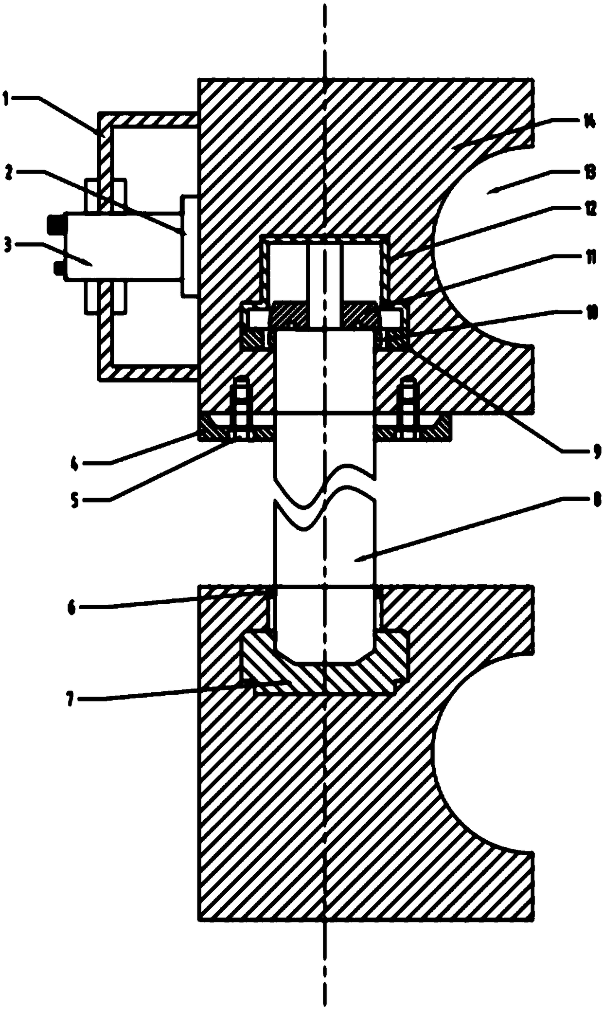
[0035] like figure 1 As shown, the installation assembly of a graded damping and vibration reduction device 8 for a rolling mill of the present invention includes a sealing end cover 4, a set screw 5, a dust-proof ring 6, an elastic adjustment pad 7, a fixed block 9, an adjustment pad 10, a stopper Push block 11, outer protective shell 12, upper work roll 13, upper work roll chock 14. The vibration sensor 3 is embedded in the sensor bracket 1 and fixedly connected to the side of the upper work roll chock 14 through the sensor base 2 .

[0036] The bottom end of the graded damping and vibration reduction device 8 is directly seated in the elastic adjustment pad 7, and is sealed with the lower work roll bearing seat by a dust-proof ring 6. The elastic adjustment pad 7 can reduce the piston rod 801 to a certain extent. itinerary.

[0037] The sealing end cover 4 is fixed o...


PUM


Abstract

The invention discloses a graded damping vibration reduction device of a rolling mill. The device comprises a vibration sensor, a damping oil cylinder and multiple electromagnetic valves; the dampingoil cylinder comprises an upper damping oil cavity and a lower damping oil cavity, each electromagnetic valve controls a flow liquid channel, the upper damping oil cavity and the lower damping oil cavity communicate through the flow liquid channels and return flow channels, floating seal valves are arranged in the flow liquid channels, the upper ends of the return flow channels are provided with the return flow channels controlled through one-way control valve pieces, vibration dynamic signal frequency is collected through a vibration sensor, the electromagnetic valves controls the flow liquidchannels corresponding to the electromagnetic valves to be opened according to the dynamic signal frequency, due to differences of oil diameters corresponding to the different electromagnetic vales,when damping liquid flows, different damping forces are generated, and graded vibration reduction of different frequency vibration of the rolling mill can be achieved.

Description

technical field [0001] The invention relates to a damping and vibration absorber, in particular to a graded damping and vibration reducing device for a rolling mill, which belongs to the technical field of rolling mill vibration reduction. Background technique [0002] With the rapid development of modern industry and various technologies, various industries have higher and higher requirements for steel surface quality. However, in the production process of steel, it is inevitable to face the vibration problem of the rolling mill. The vibration of the rolling mill will not only cause vibration marks on the strip and rolls, but also affect the production accuracy of the strip and the service life of the roll system. In severe cases, it may even cause Faults such as strip breakage and stacked steel affect the safe operation of equipment and cause huge economic losses. Therefore, the vibration suppression problem in the rolling mill production process has become a key technica...

Claims


Application Information

Patent Timeline
Patent Type & Authority Applications(China)
IPC IPC(8): F16F9/19F16F9/32F16F9/34F16F9/50F16F9/36
CPCF16F9/19F16F9/3207F16F9/3292F16F9/3405F16F9/362F16F9/50
Inventor 王桥医张秋波朱媛过山
Owner HANGZHOU DIANZI UNIV
Why Eureka
Try Eureka