Gate valve locking mechanism

A locking mechanism and gate valve technology, applied in valve details, valve devices, mechanical equipment, etc., can solve problems such as affecting the normal use of gate valves, unsatisfactory locking effect, and inconvenient locking operation, achieving ideal locking effect and improving locking efficiency. , the effect of convenient locking operation

Pending Publication Date: 2019-01-01
STATE GRID CORP OF CHINA +3
View PDF8 Cites 4 Cited by
  • Summary
  • Abstract
  • Description
  • Claims
  • Application Information

AI Technical Summary

Problems solved by technology

However, the existing gate valves are generally locked by chains and padlocks. A gate valve needs a padlock and chain, and the chain needs to be moved back and forth during operation. If there are many locked valves, there are many corresponding keys. Operators are like warehouses. Like the administrator, you need to carry a large number of keys, which is extremely inconvenient to operate
Also, the locking effect is not ideal
Moreover, when the existing gate valve is locked, its locking position often needs to be judged by experience, which may easily cause the locking position to be inaccurate, thus affecting the normal use of the gate valve.
Therefore, the prior art has the problems of inconvenient locking operation and imprecise locking position

Method used


Image

  • Gate valve locking mechanism
  • Gate valve locking mechanism
  • Gate valve locking mechanism

Examples


Embodiment Construction

[0025] The present invention will be further described below in conjunction with the accompanying drawings and embodiments, but not as a basis for limiting the present invention.

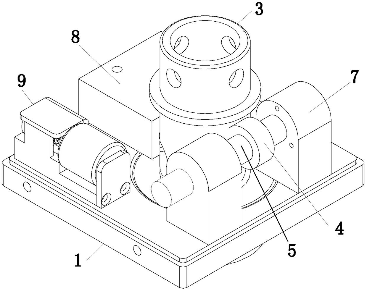
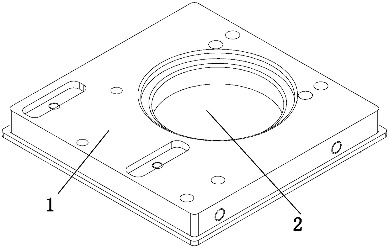
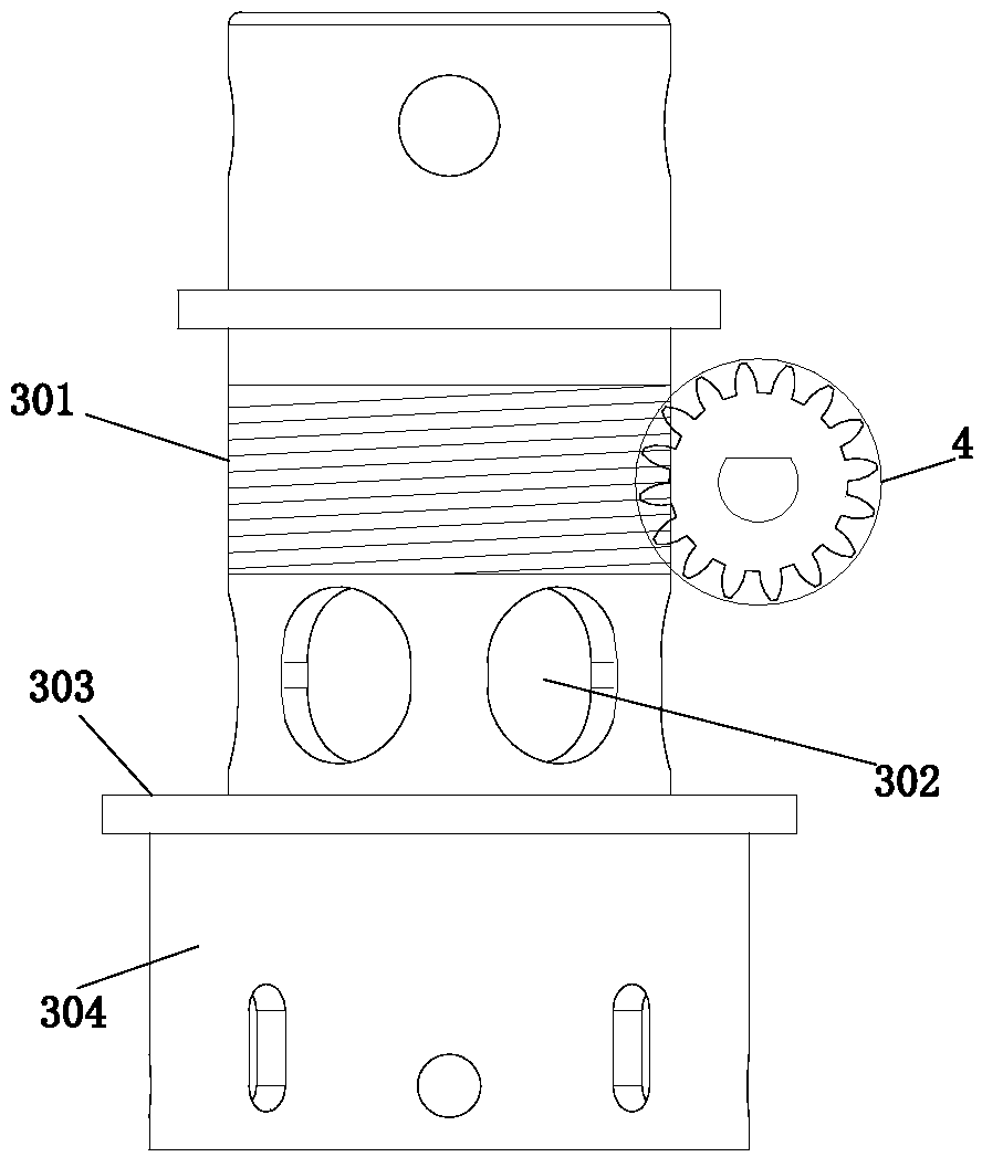
[0026] Example. A gate valve locking mechanism, constituted as Figure 1 to Figure 10 As shown, including the base 1, the middle part of the base 1 is provided with a stepped through hole 2, the stepped through hole 2 is provided with a worm 3, the side of the worm 3 is provided with a matching worm wheel 4, the worm wheel 4 is provided with a transmission shaft 5, and the transmission shaft 5 Both ends are provided with a limit worm 6, and the base 1 is provided with a mechanical memory 7 matched with the limit worm 6; the base 1 is also provided with a Bluetooth locker 8; the worm 3 includes a hollow worm body 301 The worm body 301 is provided with a locking hole 302 corresponding to the position of the Bluetooth locker 8 , a mounting plate 303 matching with the stepped through hole 2 is provided...


PUM


Abstract

The invention discloses a gate valve locking mechanism. The gate valve locking mechanism comprises a base, a stepped through hole is formed in the middle of the base, a worm is arranged in the steppedthrough hole, a worm gear matched with the worm is arranged on the side face, a transmission shaft is arranged on the worm gear, limiting worms are arranged at the two ends of the transmission rod, and the base is provided with mechanical memories matched with the limiting worms; the base is further provided with a Bluetooth locking device; and the worm comprises a worm body which is of a hollowstructure, the worm body is provided with a locking hole of which the position corresponds to that of the Bluetooth locking device, an installing disc matched with the stepped through hole is arrangedunder the locking hole, and a valve rod connecting rod is arranged on the lower portion of the worm body. The gate valve locking mechanism has the characteristics that locking operation is convenient, and the locking position precision is improved.

Description

technical field [0001] The invention relates to a gate valve locking component for a hydropower station, in particular to a gate valve locking mechanism. Background technique [0002] In hydropower plants, hidden rod gate valves are widely used in various pipelines. When the equipment or pipeline needs to be repaired, the gate valve needs to be closed and locked reliably. After the repair work is completed, the gate valve is unlocked to restore the original operating state and locked to prevent misoperation. However, the existing gate valves are generally locked by chains and padlocks. A gate valve needs a padlock and chain, and the chain needs to be moved back and forth during operation. If there are many locked valves, there are many corresponding keys. Operators are like warehouses. Like the administrator, a large number of keys need to be carried, which is extremely inconvenient to operate. Moreover, the effect of locking is not ideal. Moreover, when the existing gate...

Claims


Application Information

Patent Timeline
Patent Type & Authority Applications(China)
IPC IPC(8): F16K35/00F16K37/00
CPCF16K35/00F16K37/00
Inventor 丁光毕扬邱建峰付强张飞王义丹李逸凡
Owner STATE GRID CORP OF CHINA
Why Eureka
Try Eureka