
Liquid cooling system, and quick connector female connector

A female joint, fast technology, applied in the direction of functional valve type, lighting and heating equipment, heat exchanger sealing device, etc., can solve the problem of cooling module damage, system supply pressure instability, and the pressure in the liquid cooling module cannot be completely removed and other issues to achieve the effect of improving the service life

Active Publication Date: 2019-01-01
CHINA AVIATION OPTICAL-ELECTRICAL TECH CO LTD
View PDF5 Cites 3 Cited by
  • Summary
  • Abstract
  • Description
  • Claims
  • Application Information

AI Technical Summary

Problems solved by technology

[0003] The problems existing in the actual use of the liquid cooling system are: First, when the system is running or debugging, it is often necessary to maintain the liquid cooling module in the system, but the pressure in the liquid cooling module may not be completely relieved after the shutdown. When the liquid cooling module is transported and stored, when the ambient temperature rises, the liquid inside the module expands due to heat, and the pressure increases sharply. However, the above-mentioned female connector used on the cooling module is always in a self-sealing state, so the pressure in the cooling module cannot be released in time. Secondly, the liquid cooling system operates under the rated pressure, and the supply pressure of the system may be unstable. When the sudden change in pressure is greater than the safe pressure of the module, the cooling module will be damaged because the pressure cannot be released in time. Bulge phenomenon

Method used


Image

  • Liquid cooling system, and quick connector female connector
  • Liquid cooling system, and quick connector female connector
  • Liquid cooling system, and quick connector female connector

Examples


Embodiment Construction

[0019] Embodiments of the present invention will be further described below in conjunction with the accompanying drawings.

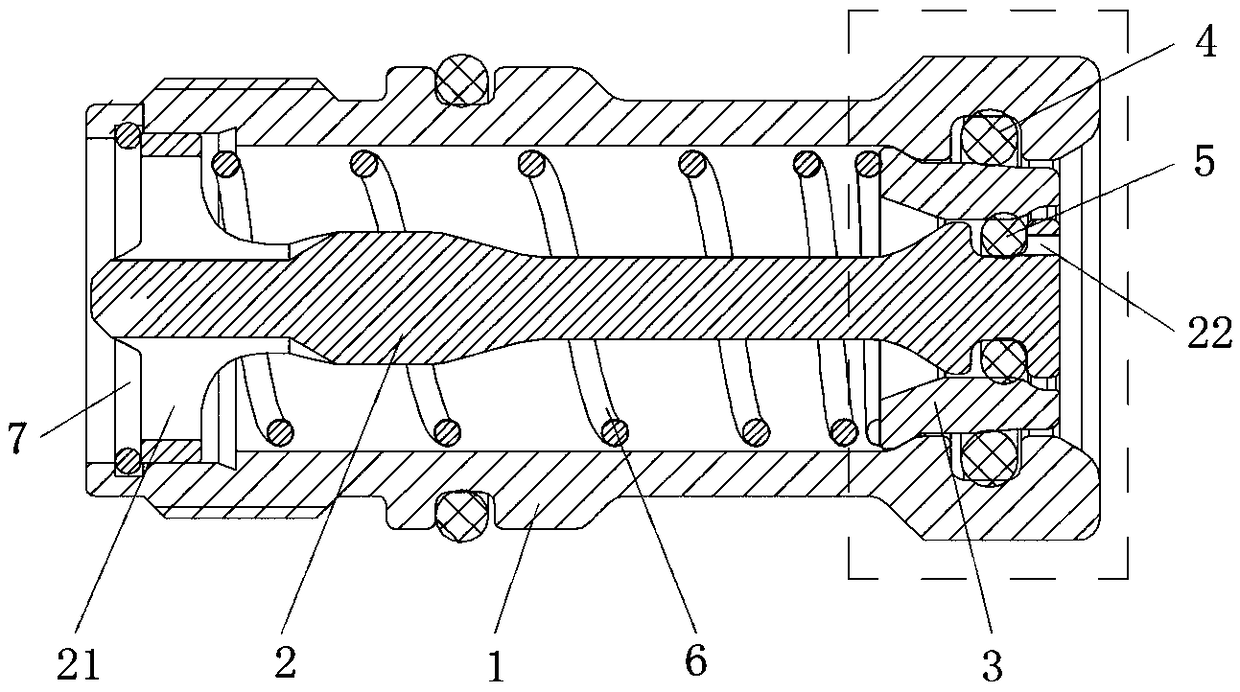
[0020] A specific embodiment 1 of a liquid cooling system of the present invention includes a cooling module, and the cooling module is provided with a quick connector female connector, and the specific structure of the quick connector female connector is as follows figure 2 As shown, it includes a cylindrical shell 1. The inner side of the cylindrical shell 1 is in the shape of a three-stage stepped hole. The diameter of the stepped hole gradually increases from the insertion end to the rear, and a front end step is formed between the small diameter section at the front end and the stepped section at the middle. The stepped surface is an inclined surface, and the rear-end stepped surface is formed between the middle stepped section and the rear-end large-diameter section.

[0021] The cylindrical housing 1 is provided with a sealing rod 2 along the axi...


PUM


Abstract

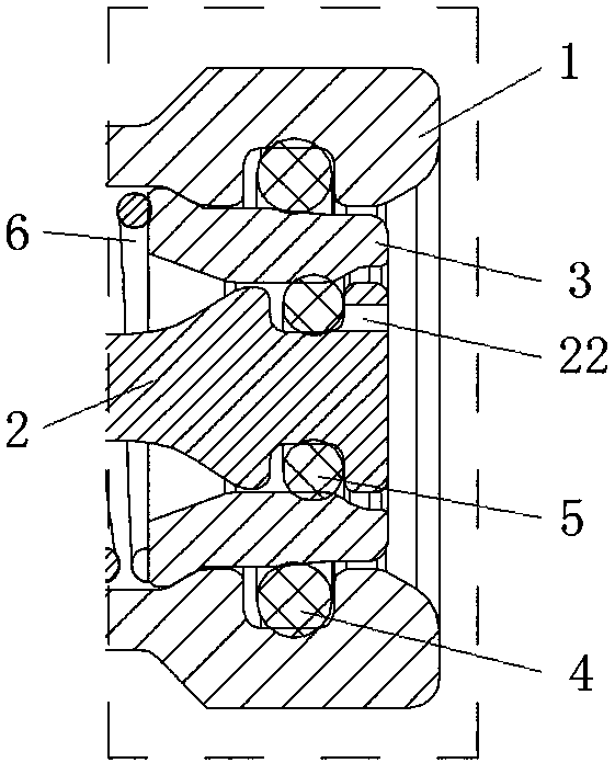
The invention relates to a liquid cooling system, and a quick connector female connector. The liquid cooling system includes a cooling module; the cooling module is provided with the quick connector female connector; the quick connector female connector includes a cylindrical shell; a sealing rod is installed in the cylindrical shell; a sealing ring is movably installed between the plugging end ofthe cylindrical shell and the sealing rod; the sealing rod is movably assembled in the cylindrical shell along an axial direction; a pressure spring whose two ends act on the sealing rod and the sealing ring to make the sealing ring keep at the position sealing a gap between the sealing rod and the cylindrical shell is installed in the cylindrical shell; and the sealing rod overcomes the action of the pressure spring to move outward and release the sealing cooperation relation with the sealing ring when internal liquid pressure is larger than a set value. The quick connector female connectorcan realize automatic pressure releasing through the axial movement of the sealing rod when the internal pressure of the cooling module rises, so that the cooling module can be prevented from being burst because of overpressure, and therefore, the service life of the liquid cooling system can be prolonged.

Description

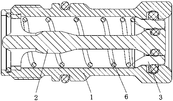
technical field [0001] The invention relates to a liquid cooling system and a quick joint female joint thereof. Background technique [0002] In liquid cooling systems, quick connectors are widely used. This is a joint that can realize pipeline connection or disconnection without tools, which brings great convenience to the installation and maintenance of liquid cooling systems. Quick connectors generally include male connectors and female connectors, and the structure of female connectors is generally as follows figure 1 As shown, it includes a cylindrical housing 1, a sealing rod 2 is fixedly installed in the cylindrical housing 1, a sealing ring 3 is arranged between the sealing rod 2 and the cylindrical housing 1, and a sealing ring 3 is arranged between the cylindrical housing 1 and the sealing ring 3. A sealing ring is arranged between the sealing rod 2 and the sealing ring 3, the sealing ring between the cylindrical housing 1 and the sealing ring 3 is located in the ...

Claims


Application Information

Patent Timeline
Patent Type & Authority Applications(China)
IPC IPC(8): F16L37/28F16K17/06F16K17/164F28F11/02F28F27/00
CPCF16K17/06F16K17/164F16L37/28F28F11/02F28F27/00
Inventor 谢地冯亚利马乐
Owner CHINA AVIATION OPTICAL-ELECTRICAL TECH CO LTD
Learn More