Air outlet device and control method and air conditioner

A technology of air outlet device and air conditioner, which is applied in the direction of airflow control components, heating methods, high-efficiency adjustment technology, etc. It can solve the problems of high wind speed and small dispersion of wind field, and achieve stable temperature control, easy conversion, and precise adjustment Effect

Pending Publication Date: 2019-01-01
NINGBO AUX ELECTRIC +1
View PDF0 Cites 9 Cited by
  • Summary
  • Abstract
  • Description
  • Claims
  • Application Information

AI Technical Summary

Problems solved by technology

[0003] In view of this, the present invention aims to propose an air outlet device to solve the problems of high wind speed, small wind field dispersion, and large air volume of current air conditioners, and improve the comfort of the air outlet of the air conditioner. more uniform temperature distribution

Method used


Image

  • Air outlet device and control method and air conditioner
  • Air outlet device and control method and air conditioner
  • Air outlet device and control method and air conditioner

Examples


Embodiment 1

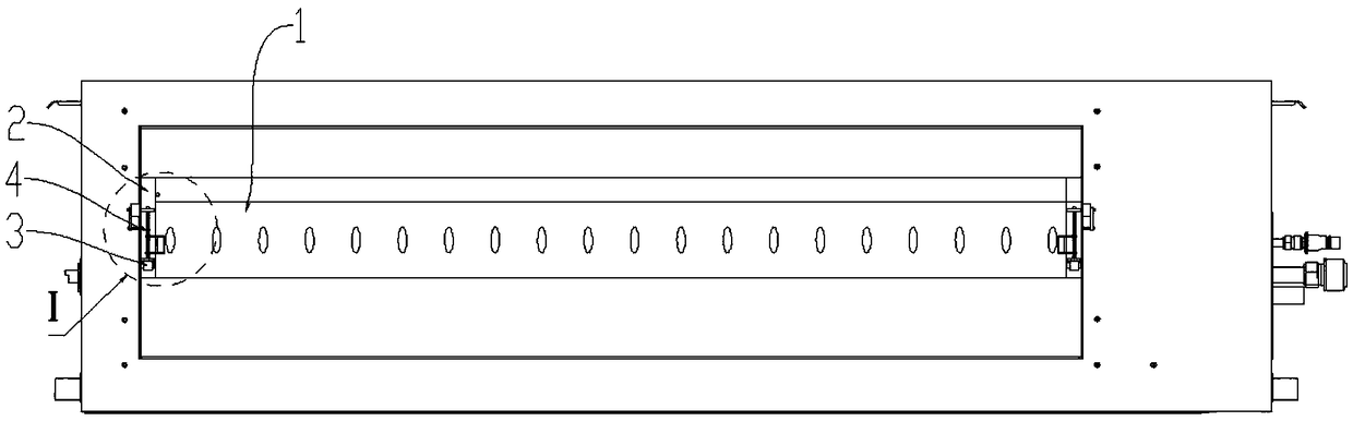
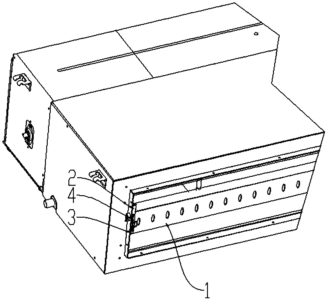
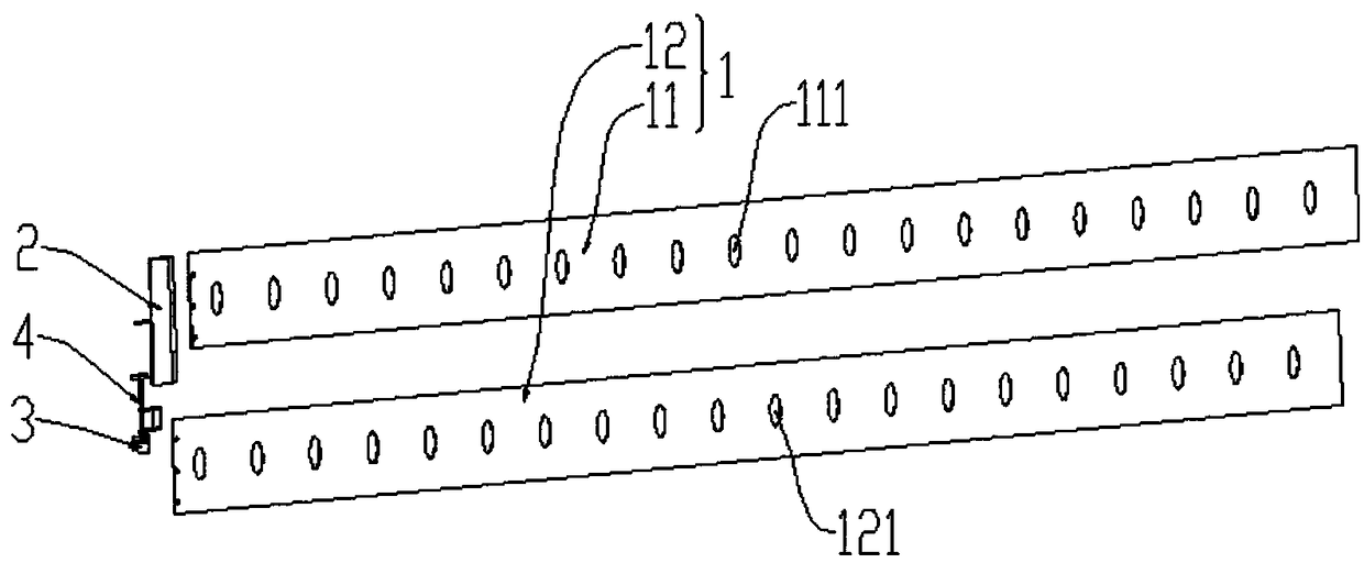
[0044] This embodiment provides an air outlet device, combined with Figure 1-Figure 4 As shown, the air outlet device includes a wind guide vane 1, a bracket 2, a first stepping motor 3 and a transmission device 4, the wind guide vane 1 is installed at the air outlet of the air conditioner, the wind guide vane 1 is a double-layer structure, and the wind guide The vane 1 is made of metal or injection molding material. Specifically, the wind guide vane 1 includes a first vane 11 and a second vane 12. The first vane 11 and the second vane 12 are both strip-shaped, and the first vane 11 and the second vane 12 are The second blade 12 is overlapped, that is, a plate surface of the first blade 11 is in contact with a plate surface of the second blade 12, and the first blade 11 is fixed on the bracket 2. Preferably, the two ends of the first blade 11 The brackets 2 are fixedly connected respectively.

[0045] The brackets 2 at both ends are provided with a first stepping motor 3 and...

Embodiment 2

[0052] On the basis of the above-mentioned embodiments, this embodiment combines Figure 6 As shown, the first through hole 111 and the second through hole 121 are both waist-shaped holes or elliptical holes, which can better control the size of the dislocation hole, and the first through hole 111 and the second through hole 121 have the same size The position where the first through hole 111 is located on the first blade 11 corresponds to the position where the second through hole 121 is located on the second blade 12, and the width D1 of the first through hole 111 and the second through hole 121 is in the range of 4-10 mm, It is preferably 6 mm, and the width D1 is the shortest inner diameter of the waist or the semi-minor diameter of the elliptical hole. In this embodiment, the width direction of the first through hole 111 is the same as the length direction of the first blade 11, and the second through hole 111 is the same as the length direction of the first blade 11. The...

Embodiment 3

[0056] On the basis of the above-mentioned embodiments, this embodiment combines Figure 4 As shown, the left end of support 2 is also provided with a second stepper motor 5, the axis of the rotating head of the second stepper motor 5 is parallel to the length direction of the wind guide vane 1, and the second stepper motor 5 is used to drive the wind guide vane 1 Make a swing.


PUM


Abstract

The invention provides an air outlet device and control method and an air conditioner, and relates to the technical field of air conditioners. The air outlet device comprises air guiding vanes, a bracket, a first stepping motor and a transmission device. The air guiding vanes comprise a first vane and a second vane, and the first vane and the second vane are in a long-strip-plate shape and arranged in an overlapped mode. The transmission device converts the rotating motion of the first stepping motor into the relative motion of the first vane and the second vane. The first vane is provided with a first through hole, the second vane is provided with a second through hole, the first through hole and the second through hole form a dislocation hole, and the relative motion of the first vane and the second vane adjusts the size of the dislocation hole. Thus, a current air supply mode is changed into multi-speed stepless speed regulation air supply, the air outlet mode of the air conditioneris effectively improved, and the control effect of the air output amount is improved, the transmission structure is simple and easy to realize, the transformation is easy, the adjustment is accurate,and air outlet is stable.

Description

technical field [0001] The invention relates to the technical field of air conditioning, in particular to an air outlet device, a control method and an air conditioner. Background technique [0002] In the prior art, when the air conditioner is running, the air outlet of the air conditioner is controlled by the swing of the blades, so as to provide cooling or heating to the environment space. However, due to the limitations of some environments and conditions, the air conditioner has a high wind speed, a small wind field dispersion, and a large air volume. When it blows directly on people, it will cause a decrease in comfort and easily cause uneven temperature distribution in the environment. Contents of the invention [0003] In view of this, the present invention aims to propose an air outlet device to solve the problems of high wind speed, small wind field dispersion, and large air volume of current air conditioners, and improve the comfort of the air outlet of the air ...

Claims


Application Information

Patent Timeline
Patent Type & Authority Applications(China)
IPC IPC(8): F24F13/14F24F11/64F24F11/74F24F11/77
CPCF24F11/64F24F11/74F24F11/77F24F13/1413Y02B30/70
Inventor 刘志财秦宪闫赞扬郑根
Owner NINGBO AUX ELECTRIC
Why Eureka
Try Eureka