Combustion chamber

A combustion chamber and air duct technology, applied in the field of combustion chamber, can solve the problems of long combustion flame, low combustion efficiency, large combustion chamber volume, etc., and achieve the effects of improving the utilization rate of heat energy, prolonging the working life, and improving the degree of atomization.

Active Publication Date: 2013-05-22
北京北机机电工业有限责任公司
View PDF7 Cites 0 Cited by
  • Summary
  • Abstract
  • Description
  • Claims
  • Application Information

AI Technical Summary

Problems solved by technology

During the working process of the existing combustion chamber, the air supply method is not perfect and the fuel atomization is not sufficient, so the combustion flame is too long, the combustion efficiency is low, and the volume of the combustion chamber is too large

Method used


Image

  • Combustion chamber
  • Combustion chamber

Examples


Embodiment Construction

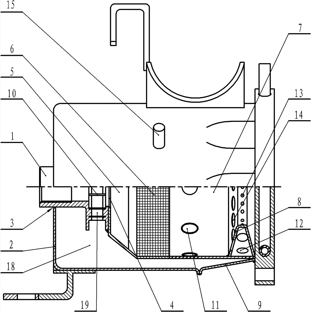
[0029] Combustion chamber of the present invention, structure such as attached figure 1As shown, it includes fuel injector seat 1, combustion chamber casing 2, front air cylinder 5, rear air cylinder 7, butterfly wind plate 8 and plum blossom cylinder 9, the connection between combustion chamber casing 2 and front air cylinder 5 and rear air cylinder 7 An air channel 18 completely surrounding the front air cylinder 5 and the rear air cylinder 7 is arranged between them, and the shell of the fuel injector seat 1 is fixedly connected with the front center hole 3 of the combustion chamber shell 2 and the central oil inlet hole 4 of the front air cylinder 5 respectively. The axis of the fuel injector seat 1 coincides with the axis of the front air cylinder 5, the fuel injection port of the fuel injector seat 1 is flush with the inner wall of the front end of the front air cylinder 5, and the fuel injector seat 1 is located outside the outer wall of the front air cylinder 5 An air ...


PUM


Abstract

A novel combustion chamber comprises an oil jet nozzle seat, a combustion chamber housing, a front air barrel, a rear air barrel and a butterfly-like air plate, wherein an air channel is arranged between the combustion chamber housing and the front air barrel and the rear air barrel; the oil jet nozzle seat is fixedly connected to the combustion chamber housing and the front air barrel, respectively; an oil jet nozzle is provided with an air inlet on which a plurality of vortex plates are evenly distributed; the rear air barrel is provided with a plurality of rear air barrel front-section airinlets and a plurality of rear air barrel rear-section air inlets, respectively; a plurality of air curtain holes are formed on the bottom of the butterfly-like air plate; a plurality of reflecting holes are formed on a side wall, facing the direction of the front air barrel, of the butterfly-like air plate; and a heat-resistant alloy fibre evaporation mesh is jointed on the internal surface of the front air barrel. The novel combustion chamber of the invention allows the air to enter the combustion chamber via the reflecting holes in a direction opposite to the direction of a combustion gas flow in the combustion chamber, so that the turbulence condition of a fuel-oil mixed gas is evener and more rational. Moreover, the heat-resistant alloy fibre evaporation mesh improves the atomizationdegree of the fuel oil and promotes the secondary evaporation of the wall-attached fuel oil, so that the combustion efficiency can stably reach 95% or higher; therefore, the energy-saving effect is very obvious.

Description

technical field [0001] The invention relates to a combustion chamber, in particular to a combustion chamber. Background technique [0002] The combustion chamber is a key device of an oil-fired boiler or an oil-fired heater. The combustion efficiency of the combustion chamber is directly related to the performance of the oil-fired heating device. In the working process of the existing combustion chamber, the air supply method is not perfect and the fuel atomization is not sufficient, so the burning flame is too long, the combustion efficiency is low, and the volume of the combustion chamber is relatively large. Contents of the invention [0003] In order to improve the air supply mode of the combustion chamber, improve the atomization effect of fuel oil, and improve the combustion efficiency of the combustion chamber, the present invention proposes a combustion chamber, and the adopted technical scheme is: [0004] Combustion chamber, including fuel injector seat, combust...

Claims


Application Information

Patent Timeline
Patent Type & Authority Patents(China)
IPC IPC(8): F23C7/00F23C3/00
Inventor 吴枫崔海玲
Owner 北京北机机电工业有限责任公司
Why Eureka
Try Eureka