Optical fiber asynchronous triggering-based high-speed rail substation-used cable partial discharge positioning device

A partial discharge and asynchronous technology, which is applied in the direction of testing dielectric strength and using optical methods, can solve the problems of signal background noise submersion, small partial discharge signal, large electromagnetic interference, etc., to achieve the elimination of time delay, low cost, The effect of low operation and maintenance costs

Pending Publication Date: 2019-01-01
CHINA CREC RAILWAY ELECTRIFICATION BUREAU GRP
View PDF1 Cites 3 Cited by
  • Summary
  • Abstract
  • Description
  • Claims
  • Application Information

AI Technical Summary

Problems solved by technology

[0002] Partial discharge is one of the important parameters for detecting insulation degradation of high-voltage power cables. It is particularly important to be able to detect correctly and have fault location. There are two main types of partial discharge location. One is the traveling wave method, which detects the original signal of partial discharge and The time difference of the signal after the signal goes back and forth is used to calculate the partial discharge position. The other is to detect the signal at both ends of the discharge source at the same time, and calculate the discharge position according to the time difference of the two synchronous signals; the traveling wave method only needs one device, and the method is simple, but On-site detection has large electromagnetic interference and small partial discharge signals, and the returned signal is easily overwhelmed by background noise, making it difficult to locate. The key to double-ended synchronous acquisition and positioning lies in the synchronization accuracy of the two devices, so most double-ended synchronous acquisition and positioning mainly lies in How to improve the synchronization accuracy of the device

Method used


Image

  • Optical fiber asynchronous triggering-based high-speed rail substation-used cable partial discharge positioning device
  • Optical fiber asynchronous triggering-based high-speed rail substation-used cable partial discharge positioning device

Examples


Embodiment

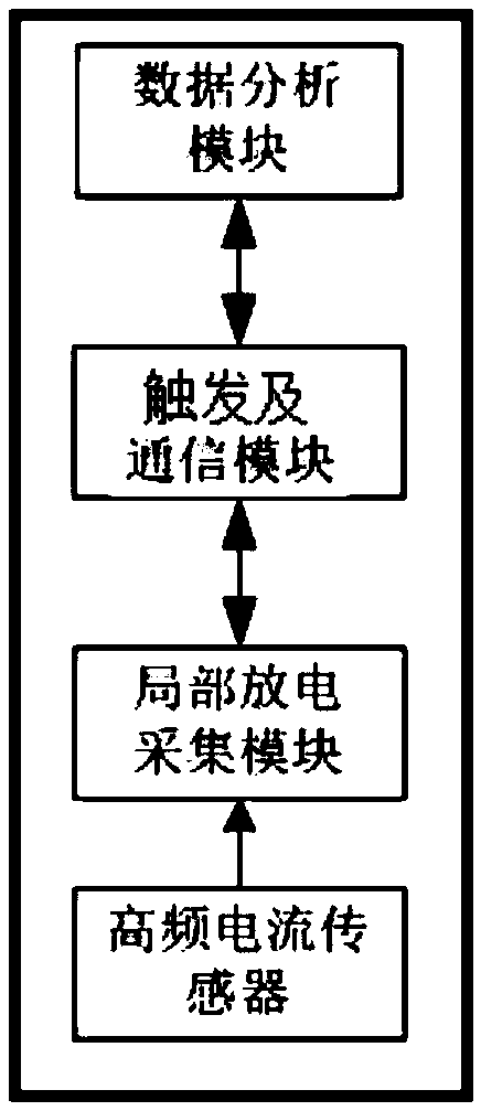
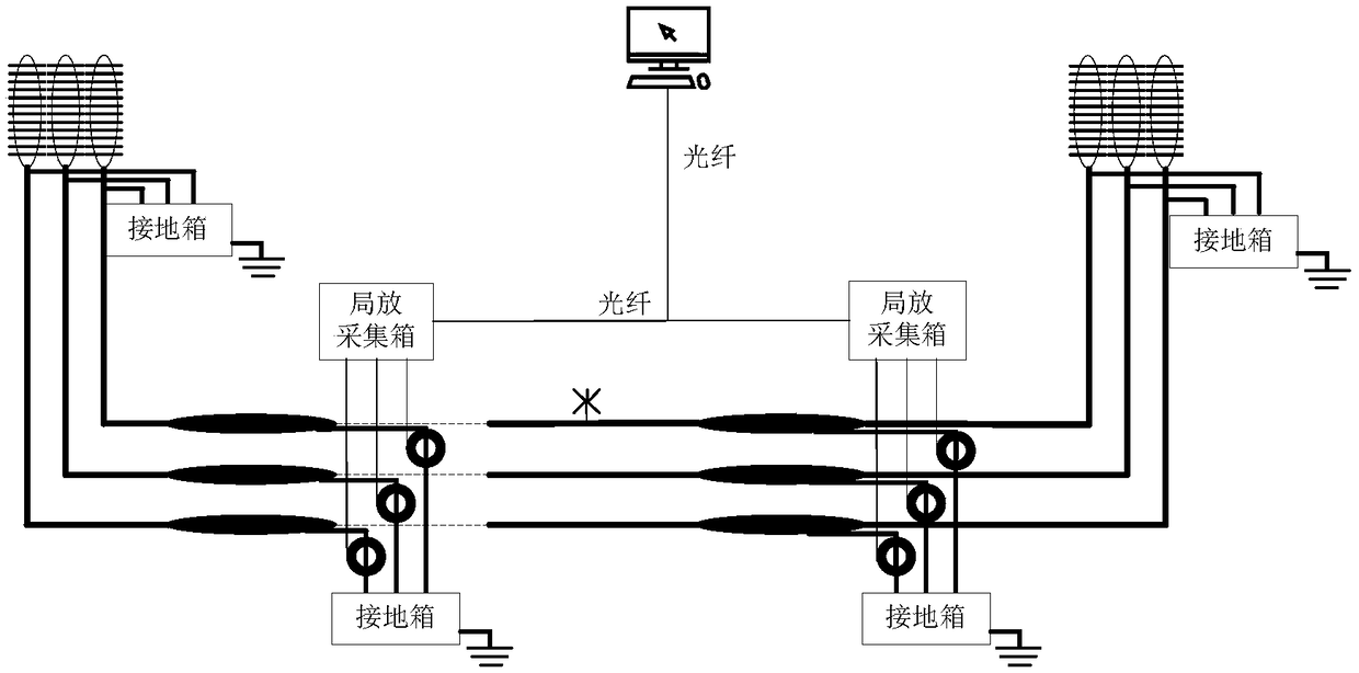
[0022] refer to figure 2 , the high-frequency current sensor is socketed on the ground wire of the three-phase cable accessory or the cross-connection ground wire; the output of the high-frequency current sensor is connected to the partial discharge acquisition module, and the partial discharge acquisition module digitally filters and amplifies the signal coupled by the sensor. , and then transmit the data to the data analysis module for analysis and processing through the trigger and communication module, calculate the time difference of the partial discharge waveform at both ends, and obtain the discharge position of the partial discharge.

[0023] The components in the system of the present invention are described one by one below:

[0024] ① The high-frequency current sensor described above uses the Rogowski coil principle to induce partial discharge signals, converts them into analog signals, and connects them to the input terminal of the partial discharge acquisition mo...


PUM


Abstract

The invention discloses an optical fiber asynchronous triggering-based high-speed rail substation-used cable partial discharge positioning device, which comprises a high-frequency current sensor, a partial discharge acquisition module, a triggering and communication module and a data analysis module, wherein the partial discharge acquisition module adopts digital filtering and amplification conditioning, partial discharge signals sensed by the high-frequency current sensor are subjected to analog-to-digital conversion, the data are then transmitted to an upper computer through the triggering and communication module, and synchronous data are calculated by data analysis by upper computer software, and partial discharge positioning is carried out. The triggering signals sequentially triggerthe acquisition devices through the optical fiber, the acquisition devices sequentially acquire partial discharge signals, the signals are then transmitted to the upper computer through the optical fiber, the upper computer can realize ns-level synchronization accuracy of the acquired data after compensation based on inherent delay between acquisition devices, and thus, partial discharge positiondiagnosis can be carried out.

Description

technical field [0001] The invention belongs to the technical field of electric cable partial discharge detection, and in particular relates to a cable partial discharge positioning device for high-speed railway substations based on optical fiber asynchronous triggering. Background technique [0002] Partial discharge is one of the important parameters for detecting insulation degradation of high-voltage power cables. It is particularly important to be able to detect correctly and have fault location. There are two main types of partial discharge location. One is the traveling wave method, which detects the original signal of partial discharge and The time difference of the signal after the signal goes back and forth is used to calculate the partial discharge position. The other is to detect the signal at both ends of the discharge source at the same time, and calculate the discharge position according to the time difference of the two synchronous signals; the traveling wave ...

Claims


Application Information

Patent Timeline
Patent Type & Authority Applications(China)
IPC IPC(8): G01R31/12
CPCG01R31/1218
Inventor 周启斌吴胜翔楚树桥周宏强呼海明宁伟宋文王玥
Owner CHINA CREC RAILWAY ELECTRIFICATION BUREAU GRP
Why Eureka
Try Eureka