
Projection lens

A projection lens and lens technology, applied in the field of optical projection, can solve problems such as coating on easily damaged lenses, lack of good protection measures for projection lenses, affecting the service life of internal lenses, etc., to achieve the effect of preventing pollution

Inactive Publication Date: 2019-01-01
XIANGYANG XIONGSHI PHOTOELECTRIC TECH CO LTD
View PDF14 Cites 0 Cited by
  • Summary
  • Abstract
  • Description
  • Claims
  • Application Information

AI Technical Summary

Problems solved by technology

[0005] Aiming at the deficiencies of the prior art, the present invention provides a projection lens, which solves the problem that the existing projection lens does not have good protection measures, and when the ambient temperature of the projection lens changes greatly, the internal lens When thermal expansion and contraction change drastically, it is easy to damage the coating on the lens and affect the service life of the internal lens

Method used


Image

  • Projection lens
  • Projection lens
  • Projection lens

Examples


Embodiment Construction

[0030] The technical solutions in the embodiments of the present invention are clearly and completely described. Obviously, the described embodiments are only some of the embodiments of the present invention, not all of them. Based on the embodiments of the present invention, all other embodiments obtained by persons of ordinary skill in the art without making creative efforts belong to the protection scope of the present invention.

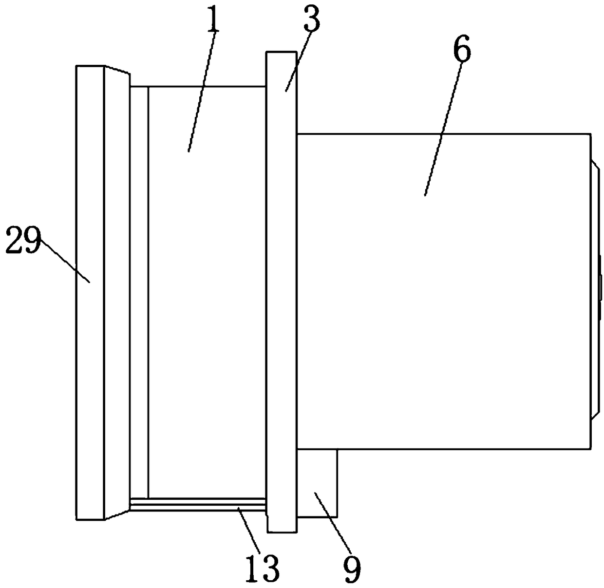
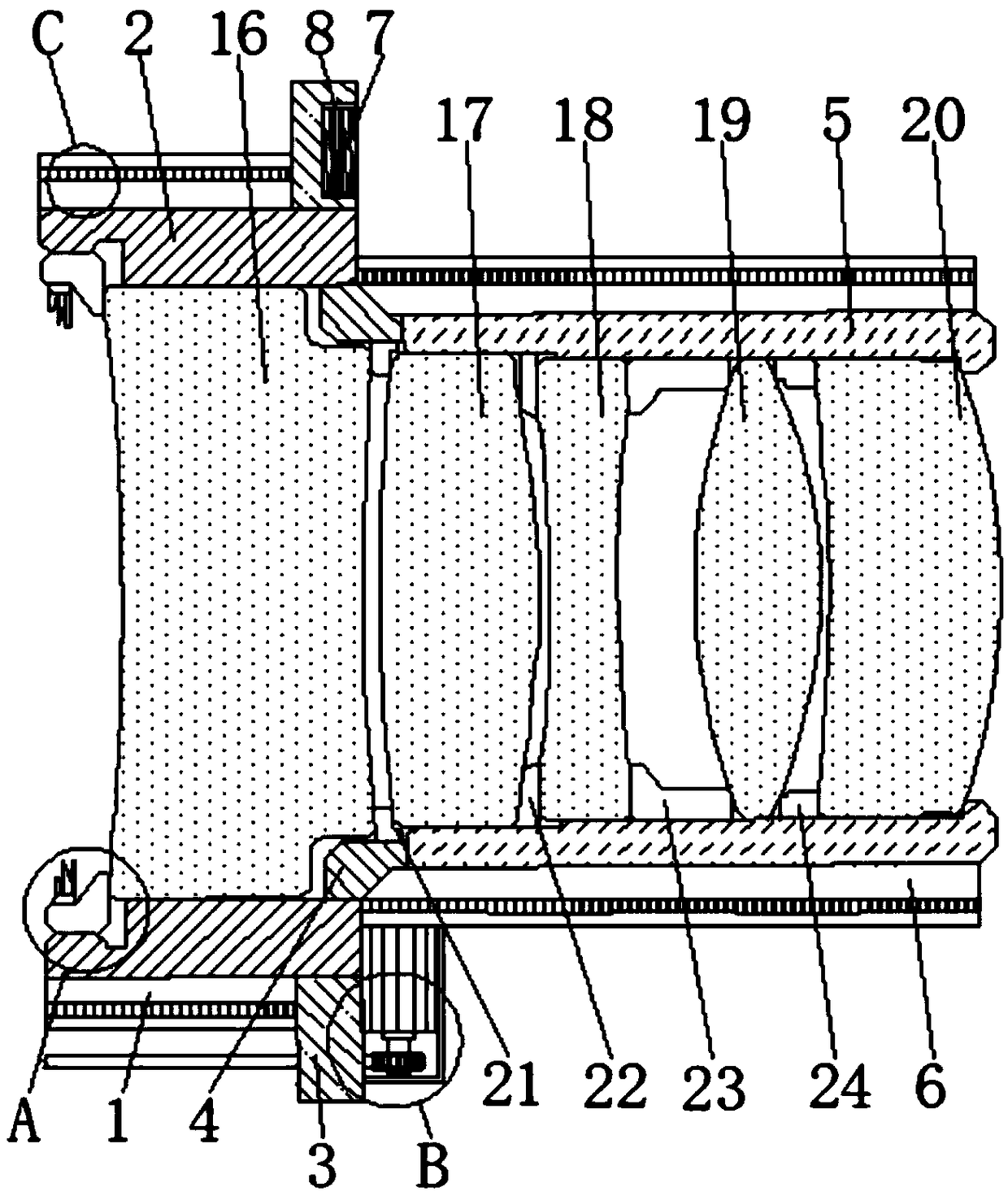
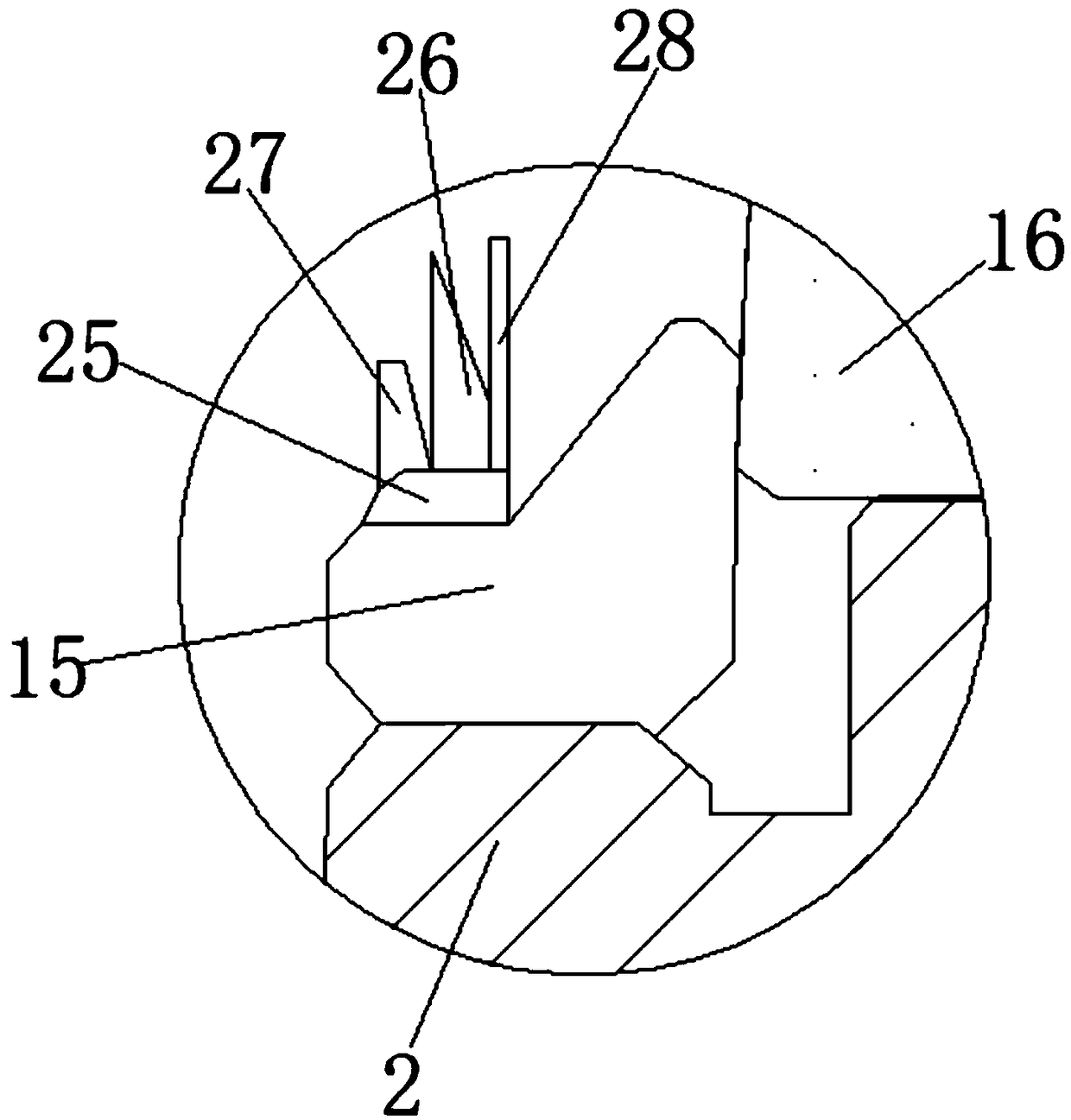
[0031] see Figure 1-7 , the embodiment of the present invention provides a technical solution: a projection lens, including a first temperature-varying buffer tube 1, the inner surface of the first temperature-varying buffer tube 1 is fixedly connected with a first lens fixing sleeve 2, and the first lens is fixed The right side of the outer surface of the sleeve 2 and the right side of the first temperature-changing buffer tube 1 are fixedly connected with a circular outer sleeve plate 3, and the right side of the inner surface of the first len...


PUM


Abstract

The invention discloses a projection lens comprising a first temperature-variation buffer tube. A first lens fixation casing tube is fixedly connected to the inner surface of the first temperature-variation buffer tube; a circular externally connected sleeving board is fixedly connected at the right side of the outer surface of the first lens fixation casing tube and the right side of the first temperature-variation buffer tube; a second lens fixation casing tube is fixedly connected to the right side of the inner surface of the first lens fixation casing tube by a rigid connection ring; and asecond temperature-variation buffer tube is fixedly connected at the outer surfaces of the second lens fixation casing tube and the rigid connection ring at the right side of the first lens fixationcasing tube. Besides, an external connecting fixation hole is formed in the top of the right side of the circular externally connected sleeving board. The projection lens relates to the technical field of optical projection. With the projection lens, a problem that the existing projection lens has not good protection measures can be solved. With an annular lens cover, a lens piece arranged at a projection end of the projection lens can be protected well; and the size of a light emitting hole of the projection lens can be controlled to prevent the pollution on the lens by external dust.

Description

technical field [0001] The invention relates to the technical field of optical projection, in particular to a projection lens. Background technique [0002] The aperture of the lens is represented by a numerical value, and the maximum aperture of each lens is marked in front of the lens with a numerical value. The size of the aperture f-number, f is the light transmittance of the lens. The larger the aperture f (the smaller the f value), the greater the light transmittance of the lens. If a lens is set with multiple apertures, the larger the aperture value, the smaller the aperture and the less luminous flux. What I want to explain here is that the f value of the lens can reach a value of 1.0 under ideal conditions. Due to the constraints of manufacturing technology and price factors, the f value can never reach 1.0. For a projector, the lens is the last link in the optical path of the projector. Whether the lens is good or not, and whether the aperture value can be minim...

Claims


Application Information

Patent Timeline
IPC IPC(8): G02B7/02G03B21/14
CPCG02B7/021G03B21/14
Inventor 张龙聂新旺邢广东古文斌
Owner XIANGYANG XIONGSHI PHOTOELECTRIC TECH CO LTD
Learn More