Automatic feeding device for chicken breeding

An automatic feeding device and feeding technology, applied in the field of chicken breeding equipment, can solve the problems of low degree of automation, inconvenient feeding, easy to catch cold and sick, and achieve the effect of controllable feeding speed, flexible use and ensuring healthy growth.

Inactive Publication Date: 2019-01-04
温碧君
View PDF9 Cites 3 Cited by
  • Summary
  • Abstract
  • Description
  • Claims
  • Application Information

AI Technical Summary

Problems solved by technology

At present, when breeding chickens and ducks, water and feed are usually stirred and mixed manually, which has a low degree of automation and cannot increase the temperature of feed and food. Especially in winter, when chickens and ducks eat colder food, they are prone to cold and disease. Moreover, manual feeding is difficult to control the speed and amount of feeding, and it is inconvenient to feed according to demand

Method used


Image

  • Automatic feeding device for chicken breeding
  • Automatic feeding device for chicken breeding
  • Automatic feeding device for chicken breeding

Examples


Embodiment 1

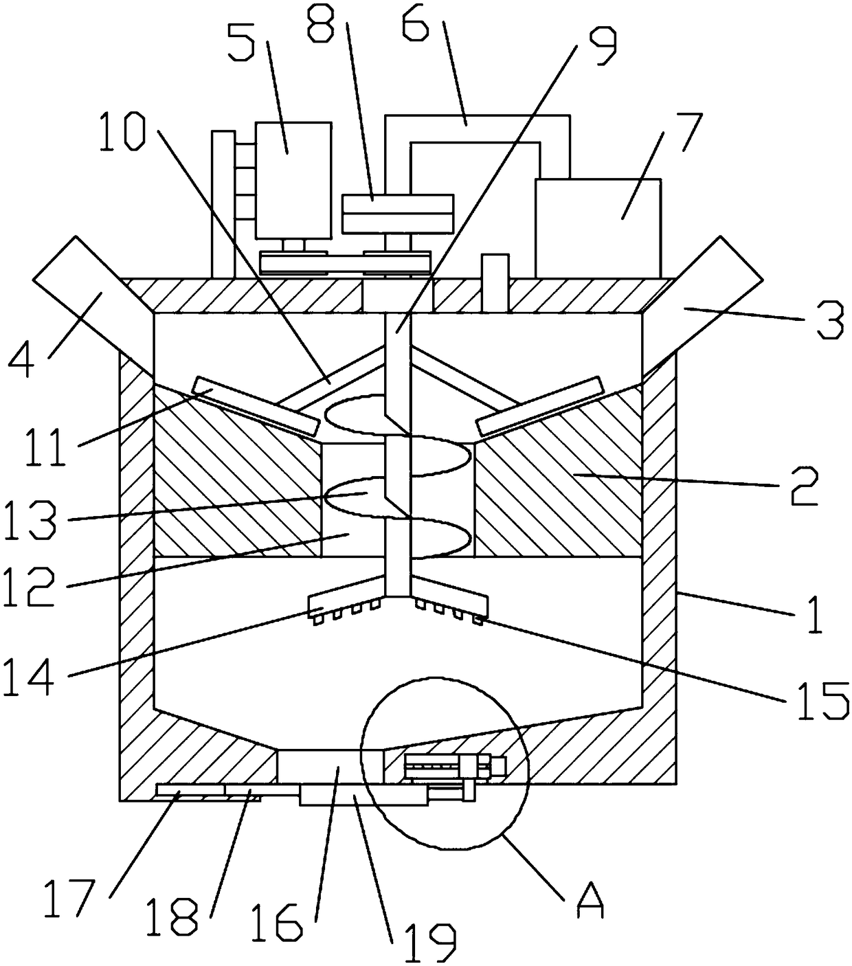
[0020] see Figure 1~3 , in the embodiment of the present invention, an automatic feeding device for chicken breeding, comprising a box body 1, a partition plate 2 is fixedly arranged inside the box body 1, and the upper surface of the partition plate 2 is arranged at an inclination with the middle low and the two ends high, The middle part of the dividing plate 2 is provided with a blanking channel 12, and a rotating rod 9 is penetrated in the discharging channel 12, and the top of the rotating rod 9 is rotated through the top plate of the casing 1, and the upper part of the rotating rod 9 A support rod 10 is fixedly installed on the outer ring, and the bottom end of the support rod 10 is fixedly connected with a stirring rod 11 matched with the inclined surface of the upper surface of the partition plate 2, and a spiral blade 13 is arranged on the rotating rod 9 inside the spiral blade 13. The stirring motor 5 that is used to drive the rotating rod 9 to rotate is fixedly ins...

Embodiment 2

[0025] Different from Embodiment 1, the rotating rod 9 adopts a hollow tube, and a hot air blower 7 is fixedly installed on the top plate of the box body 1, and the air outlet end of the hot air blower 7 is connected with a vent pipe 6, and the other end of the vent pipe 6 is connected to the air pipe 6. The tops of the rotating rods 9 are rotatably connected by a rotary joint 8, and the bottom end of the rotating rods 9 in the casing 1 is fixedly equipped with an exhaust pipe 14. The exhaust pipe 14 adopts a hollow pipe, and the inner part of the exhaust pipe 14 The cavity communicates with the lower inner cavity of the rotating rod 9. Further, the lower surface of the exhaust pipe 14 is equidistantly provided with a number of blowing ports 15 for discharging the air in the exhaust pipe 14. In this embodiment, the heat The hot air that blower fan 7 produces is injected in the rotating bar 9 through vent pipe 6, and then the hot air in rotating bar 9 is discharged by blowing po...


PUM


Abstract

The invention relates to the technical field of chicken breeding equipment, specifically to an automatic feeding device for chicken breeding. The automatic feeding device comprises a box body, whereina partition plate is fixedly arranged in the box body; the central part of the partition plate is provided with a blanking channel; a rotating rod penetrates through and is arranged in the blanking channel; the top part of the rotating rod rotatably penetrates through the top plate of the box body; the outer ring of the upper end of the rotating rod is fixedly provided with supporting rods; the bottom end of each supporting rod is fixedly connected with a stirring rod; the rotating rod located in the box body is provided with a spiral blade; a discharge outlet is arranged on the bottom plateof the inner chamber of the box body; and a material blocking mechanism used for controlling the discharge speed of the discharge outlet is arranged on the bottom plate of the box body. The automaticfeeding device provided by the invention has good mixing effect to a feed, can realize controllability of the discharging speed of the feed, is flexible to use, can heat a feed mixture in the box body, and guarantees healthy growth of chickens.

Description

technical field [0001] The invention relates to the technical field of chicken breeding equipment, in particular to an automatic feeding device for chicken breeding. Background technique [0002] Breeding includes livestock farming, poultry farming, aquaculture and special farming. [0003] With the continuous improvement of people's living standards, the demand for chicken and duck meat is also increasing. Coupled with the improvement of rural living conditions and the development of agricultural production mechanization, chickens and ducks have gradually withdrawn from family farming. At present, when breeding chickens and ducks, water and feed are usually stirred and mixed manually, which has a low degree of automation and cannot increase the temperature of feed and food. Especially in winter, when chickens and ducks eat colder food, they are prone to cold and disease. Moreover, manual feeding is difficult to control the speed and amount of feeding, and it is inconvenien...

Claims


Application Information

Patent Timeline
Patent Type & Authority Applications(China)
IPC IPC(8): A01K39/012
CPCA01K39/0125
Inventor 温碧君
Owner 温碧君
Why Eureka
Try Eureka