Channel steel plate manufacturing bending die and application method

A channel-shaped steel plate, punching and bending technology, applied in the direction of forming tools, manufacturing tools, metal processing equipment, etc., can solve the problems of inability to safely and efficiently produce channel-shaped steel plates, potential safety hazards, and small groove-shaped nail workpieces, etc., to achieve improvement Effects on productivity and quality levels

Inactive Publication Date: 2019-01-04
ANHUI HONGYUAN IRON TOWER
View PDF0 Cites 0 Cited by
  • Summary
  • Abstract
  • Description
  • Claims
  • Application Information

AI Technical Summary

Problems solved by technology

[0002] Due to the small size of the grooved nails, there is a certain strength and rebound coefficient when the steel plate is used for bending. It is difficult to take out the formed grooved workpieces from the bending mold. Usually, hammers are used to knock out the workpieces, which is inefficient and has potential safety hazards.
To sum up, the existing molds cannot safely and efficiently produce channel-shaped steel plates that are actually required. It requires a lot of manpower, material resources and time investment to ensure quality, and the pass rate of workpieces is low. Therefore, a channel-shaped steel plate is needed to make punching and bending die Making Channel Steel Plates

Method used


Image

  • Channel steel plate manufacturing bending die and application method
  • Channel steel plate manufacturing bending die and application method

Examples


Embodiment Construction

[0017] The present invention will be described in detail below in conjunction with the accompanying drawings.

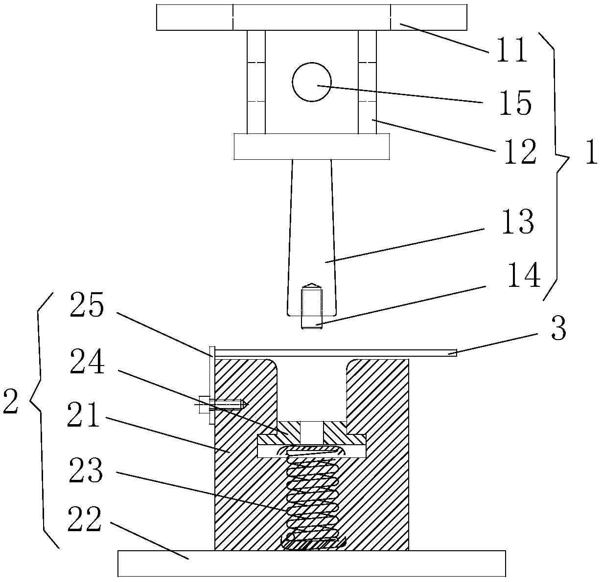
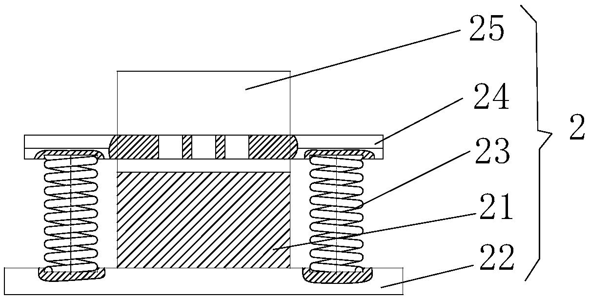
[0018] Such as Figure 1-2 as shown, figure 1 It is a structural schematic diagram of an embodiment of a punching and bending die for a channel-shaped steel plate of the present invention; figure 2 A side view of the structure of the lower die for the embodiment of a punching and bending die for a channel-shaped steel plate of the present invention

[0019] A punching and bending die for making a grooved steel plate of the present invention comprises an upper die 1 and a lower die 2;

[0020] The upper die 1 is a T-shaped structure, and the upper die 1 includes an upper die top plate 11, an extension section 12, a punching and bending contact portion 13 and a workpiece hole positioning device 14, and the extension section 12 is arranged below the upper die top plate 11, The punching and bending contact part 13 is arranged under the extension section 12, and the w...


PUM


Abstract

The invention provides a channel steel plate manufacturing bending die. The channel steel plate manufacturing bending die comprises an upper die and a lower die. The upper die is of a T-shaped structure, and comprises an upper die top plate, an extending section, a bending contact portion and a workpiece hole locating device. The extending section is arranged at the bottom of the upper die top plate, the bending contact portion is arranged at the bottom of the extending section, and the workpiece hole locating device is fixedly arranged at the bottom end of the bending contact portion. The lower die is of a U-shaped structure, and comprises a lower die bending base body, a lower die base plate, material removal compression springs, a material removal plate and a baffle. The lower die bending base body is arranged on the top of the lower die base plate, the material removal compression springs are arranged on the lower die base plate and located on the two sides of the lower die bendingbase body, the material removal plate is fixedly arranged on the tops of the material removal compression springs on the two sides, and the baffle is arranged on the side face of the lower die bending base body and connected with the lower die bending base body through bolts. The channel steel plate manufacturing bending die effectively accomplishes steel plate bending and effective material removal, eliminates the workpiece hammering taking mode, and is safe and efficient.

Description

technical field [0001] The invention relates to the field of steel plates for making foot nails for power transmission lines, in particular to a punching and bending die for making groove-shaped steel plates and a use method thereof. Background technique [0002] Due to the small size of the grooved foot nails, there is a certain strength and rebound coefficient when the steel plate is used for bending. It is difficult to take out the formed grooved workpieces from the bending mold. Usually, hammers are used to knock them out, which is inefficient and has potential safety hazards. To sum up, the existing molds cannot safely and efficiently produce channel-shaped steel plates that are actually required. It requires a lot of manpower, material resources and time investment to ensure quality, and the pass rate of workpieces is low. Therefore, a channel-shaped steel plate is needed to make punching and bending die Make channel steel plates. Contents of the invention [0003] ...

Claims


Application Information

Patent Timeline
Patent Type & Authority Applications(China)
IPC IPC(8): B21D37/10B21D43/00B21D45/04
CPCB21D37/10B21D43/003B21D45/04
Inventor 赵雪建刘星星管孝成
Owner ANHUI HONGYUAN IRON TOWER
Why Eureka
Try Eureka