High Power Fiber Stripper

A mold stripper and high-power technology, which is applied in the field of high-power optical fiber mold strippers, can solve problems that affect the quality of the laser and the laser does not meet the requirements, and achieve the effect of improving the bearing capacity

Active Publication Date: 2015-08-26
MAXPHOTONICS CORP
View PDF6 Cites 0 Cited by
  • Summary
  • Abstract
  • Description
  • Claims
  • Application Information

AI Technical Summary

Problems solved by technology

During the laser transmission process, the pump light and high-order mode light in the fiber cladding will seriously affect the quality of the laser, resulting in the laser output from the fiber laser not meeting the requirements
There is no special device in the existing technology to solve this problem, which largely prevents the development of fiber lasers to higher power

Method used


Image

  • High Power Fiber Stripper
  • High Power Fiber Stripper
  • High Power Fiber Stripper

Examples


Embodiment 1

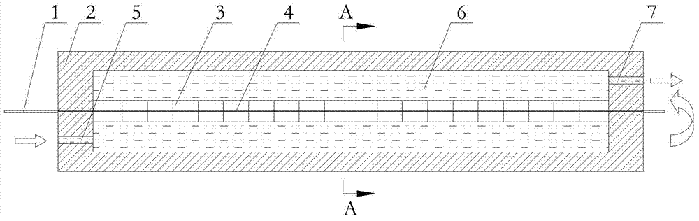
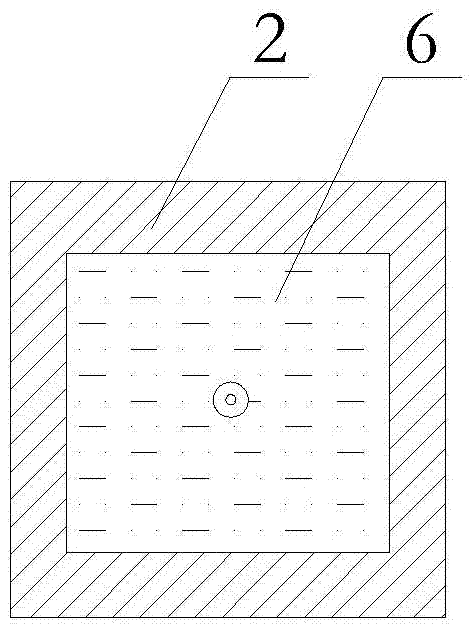
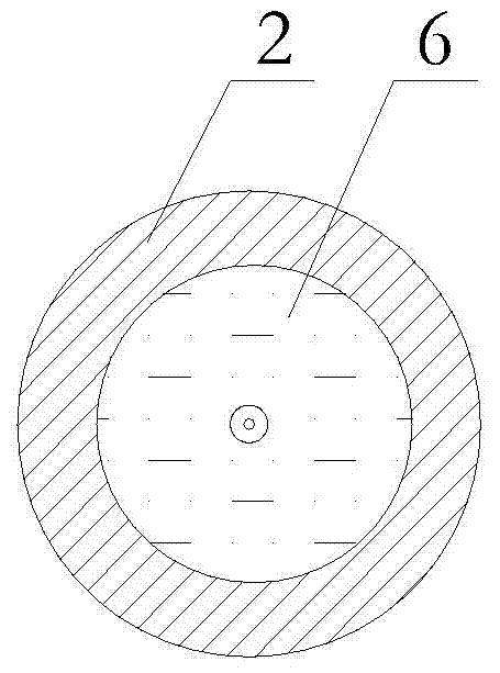
[0017] Embodiment 1 of the present invention: a high-power optical fiber stripper, comprising a double-clad optical fiber 1 and a packaging device 2, the middle part of the double-clad optical fiber 1 is provided with a decoated optical fiber 4, and a decoated optical fiber 4 is provided with There are multiple layers of adhesive layers 3 , a cooling chamber 6 is provided in the packaging device 2 , and the decoated optical fiber 4 is provided in the cooling chamber 6 . The multi-level adhesive layer 3 is composed of adhesive layer units with different refractive indices juxtaposed. The adhesive layer unit is arranged on the decoated optical fiber 4 in the order of the refractive indices N1, N2, N3...Nn...N3, N2, N1. The refractive index of the adhesive layer unit satisfies N1

Embodiment 2

[0018] Embodiment 2 of the present invention: a high-power optical fiber stripper, including a double-clad optical fiber 1 and a packaging device 2, the middle part of the double-clad optical fiber 1 is provided with a decoated optical fiber 4, and a decoated optical fiber 4 is provided with There are multiple layers of adhesive layers 3 , a cooling chamber 6 is provided in the packaging device 2 , and the decoated optical fiber 4 is provided in the cooling chamber 6 . The multi-level adhesive layer 3 is composed of adhesive layer units with different refractive indices juxtaposed. The adhesive layer unit is arranged on the decoated optical fiber 4 in the order of the refractive indices N1, N2, N3...Nn...N3, N2, N1. The refractive index of the adhesive layer unit satisfies N1

Embodiment 3

[0019] Embodiment 3 of the present invention: a high-power optical fiber stripper, comprising a double-clad optical fiber 1 and a packaging device 2, the middle part of the double-clad optical fiber 1 is provided with a coating-free optical fiber 4, and the coating-free optical fiber 4 is provided with a There are multiple layers of adhesive layers 3 , a cooling chamber 6 is provided in the packaging device 2 , and the decoated optical fiber 4 is provided in the cooling chamber 6 . The multi-level adhesive layer 3 is composed of adhesive layer units with different refractive indices juxtaposed. The adhesive layer unit is arranged on the decoated optical fiber 4 in the order of the refractive indices N1, N2, N3...Nn...N3, N2, N1. The refractive index of the adhesive layer unit satisfies N1


PUM


Abstract

The invention discloses a high-power fiber mode stripper comprising a double-clad fiber 1 and a packaging device 2. A coating layer removing fiber 4 is arranged in the middle of the double-clad fiber 1, a multistage adhesive layer 3 is arranged on the coating layer removing fiber 4, a cooling chamber 6 is arranged in the packaging device 2, and the coating layer removing fiber 4 is arranged in the cooling chamber 6. The multistage adhesive layer 3 is composed of adhesive layer units different in refractive index. Compared with the prior art, the high-power fiber mode stripper has the advantages that harmful light such as high-order mode light and residual pump light generated by light in fiber claddings can be effectively stripped through the multi-stage adhesive layer, heat converted from the harmful light is absorbed and brought out through cooling media in the packaging device, bearing capacity of the mode stripper to high-power laser light is improved greatly, and the mode stripper can bear hectowatt laser light, and can be applied to a kilowatt-class or myriawatt-class fiber laser. Meanwhile, safety of the fiber laseris improved to a great degree, and service life of the fiber laser is prolonged greatly.

Description

technical field [0001] The invention relates to a high-power optical fiber mold stripper, which is mainly used in the field of high-power fiber lasers of 100W to 10,000W, especially in the field of high-power fiber lasers. Background technique [0002] A fiber laser is mainly composed of three basic elements: a pump source, a gain medium, and a resonator. The pump source is mainly a high-power semiconductor laser, and the gain medium is a rare-earth-doped double-clad fiber. The resonator can be composed of various linear resonators such as optical feedback elements such as fiber gratings, and various ring resonators can also be formed by couplers. . The pump light is coupled into the gain fiber through an appropriate optical system. After absorbing the pump light, the gain fiber forms population inversion or nonlinear gain and generates spontaneous emission. Finally, a stable laser output is formed. During the laser transmission process, the pump light and high-order mode...

Claims


Application Information

Patent Timeline
Patent Type & Authority Patents(China)
IPC IPC(8): G02B6/245H01S3/067
Inventor 李刚胡小波
Owner MAXPHOTONICS CORP
Why Eureka
Try Eureka