Workpiece tray rack

A material tray and rack body technology, which is applied in the field of automatic production auxiliary equipment, can solve the problem that the material tray is easy to slip out, and achieve the effect of improving work efficiency and facilitating handling work

Pending Publication Date: 2019-01-04
SUZHOU RS TECH
View PDF0 Cites 7 Cited by
  • Summary
  • Abstract
  • Description
  • Claims
  • Application Information

AI Technical Summary

Problems solved by technology

[0005] Therefore, the technical problem to be solved by the present invention is to overcome the defect that the multi-layer t

Method used


Image

  • Workpiece tray rack
  • Workpiece tray rack
  • Workpiece tray rack

Examples


Example Embodiment

[0044] Example 1

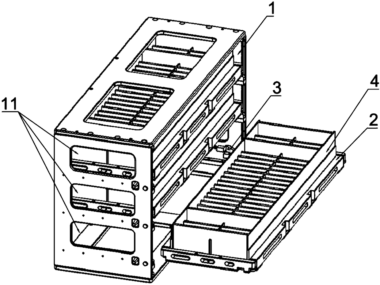
[0045] This embodiment provides a tray rack with a structure such as figure 1 As shown, it includes a main frame body 1, a bracket 2, and a material tray 3. The main frame body 1 has a storage space that can accommodate a plurality of material trays 3, and the storage space is divided into a plurality of placement layers 11 along the vertical direction. Each placement layer 11 is provided with a bracket 2 for carrying the material tray 3, and the placement layer 11 is removed from the side of the main frame 1 in the horizontal direction; it has a storage position in the placement layer 11 and a completely removed placement layer 11 Feeding position. Such as figure 1 In the three-layer bracket 2 shown, the lowest layer is in the feeding position, and the upper two layers are in the storage position.

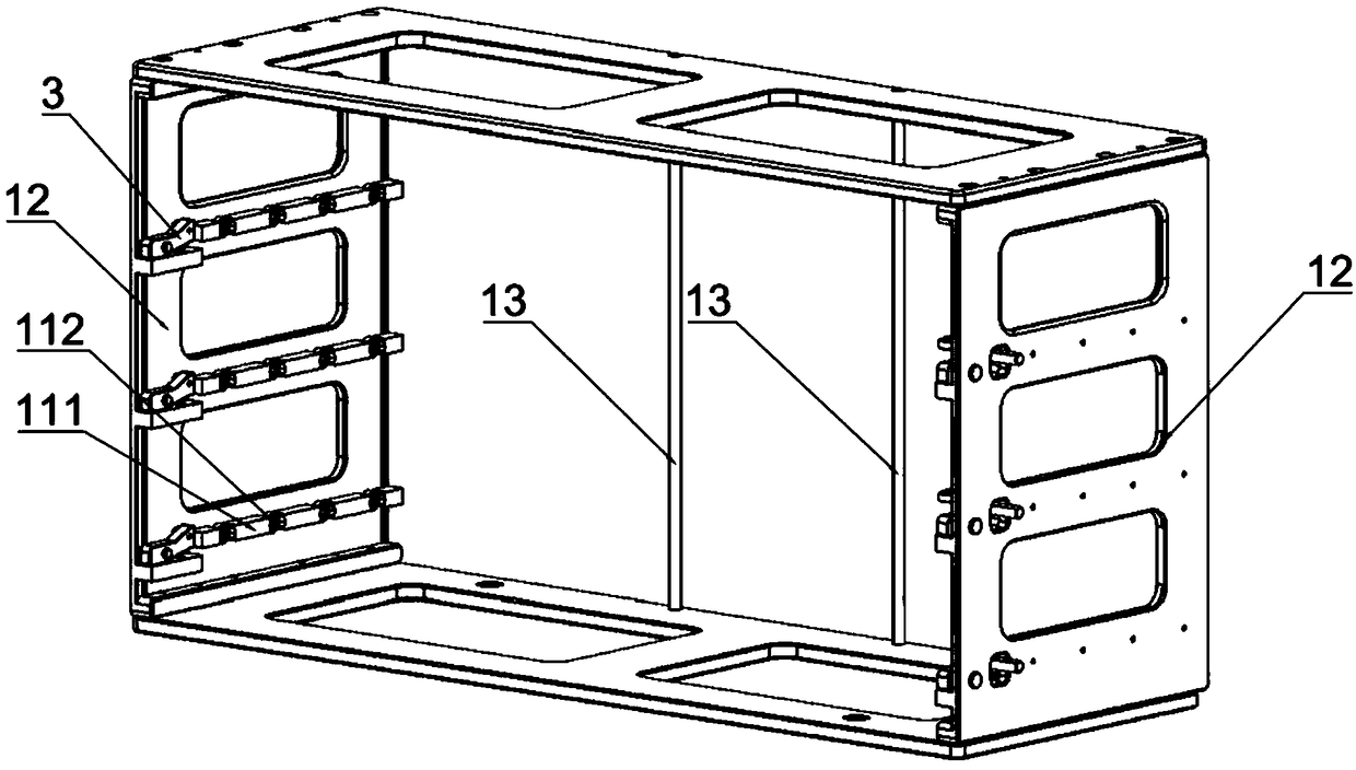
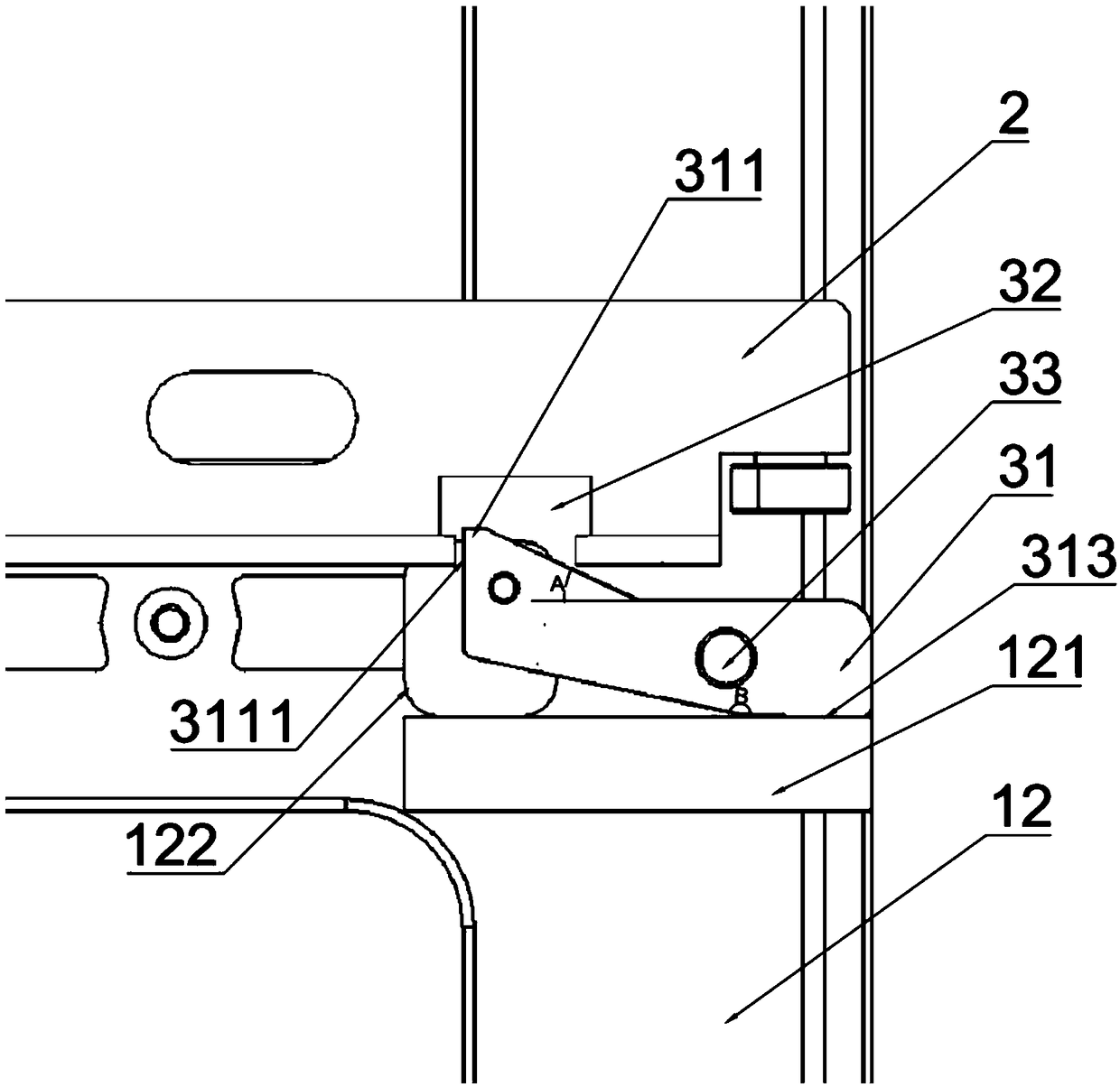
[0046] Such as Figure 2 to Figure 4 As shown, each placement layer 11 in this embodiment is provided with a locking mechanism 3 for restricting movement of the br...


PUM


Abstract

The invention provides a workpiece tray rack. The workpiece tray rack comprises a main rack body which is provided with a plurality of storing layers, and a supporting frame which is arranged in eachstoring layer and is used for bearing a workpiece tray, wherein the supporting frames are used for moving out the storing layer from one side of the main rack body in the horizontal direction; a storing position which is positioned in each storing layer and a workpiece supplying position where each storing layer can be completely moved are provided; a locking mechanism arranged in each storing layer is capable of locking the bottom part of each supporting frame through locking parts on locking blocks; the locking parts are provided with locking states that the locking parts enter locking holesand unlocking states that the locking parts are at the outer parts of the locking holes; when the supporting frames are at the storing positions, the locking parts are in the locking states; when thesupporting frames are outwards pulled again, the locking holes in the bottom parts of the supporting frames are limited by the locking parts, so that the supporting frames cannot continuously outwards slide. Therefore, each supporting frame in the workpiece tray rack is at the storing position in the whole workpiece tray rack carrying process, and as a result, workpieces in trays cannot fall off;the carrying work is conveniently carried out; and the working efficiency is improved.

Description

technical field [0001] The invention relates to the technical field of automatic production auxiliary equipment, in particular to a tray rack. Background technique [0002] The feeding tray is an auxiliary equipment of automatic assembly machinery, which can discharge various products in an orderly manner. It can cooperate with automatic assembly equipment to assemble various parts of the product into a complete product. When assembling large batches of workpieces, multiple trays are usually stacked together and placed in the feeding device to be taken layer by layer. [0003] Existing a kind of tray placement frame. Its structure includes a shell and several tray placement layers. The tray placement layer is vertically provided with several stoppers, connecting rods are arranged between the adjacent stoppers, and the connecting rods and stoppers form a tray placement position. The distance between the connecting rod and the end of the adjacent tray placement layer is less...

Claims


Application Information

Patent Timeline
IPC IPC(8): B23P19/00B25H3/04
CPCB23P19/00B25H3/04
Inventor 吴加富缪磊高冬青冯小平郑俊杰
Owner SUZHOU RS TECH
Why Eureka
Try Eureka