Log distributing and guiding sending device for traditional Chinese medicinal material planting
A technology of traditional Chinese medicinal materials and logs, which is applied in the field of log distribution and conveying devices for planting traditional Chinese medicinal materials, and can solve the problems of being unsuitable for large-scale planting and promotion of Poria cocos medicinal materials, low processing efficiency, and low efficiency of manual base wood processing.
- Summary
- Abstract
- Description
- Claims
- Application Information
AI Technical Summary
Problems solved by technology
Method used
Image

Examples
Embodiment Construction
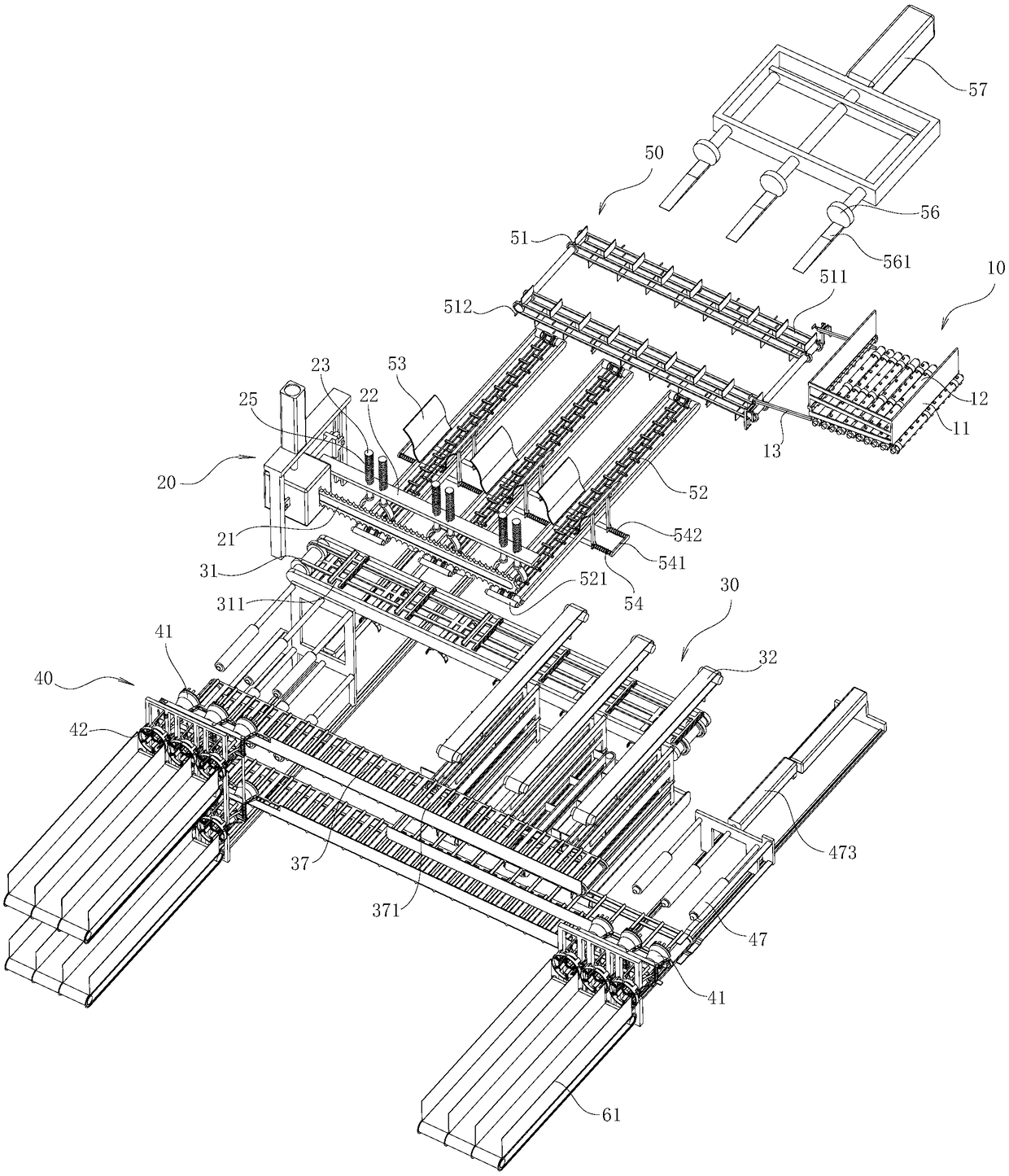
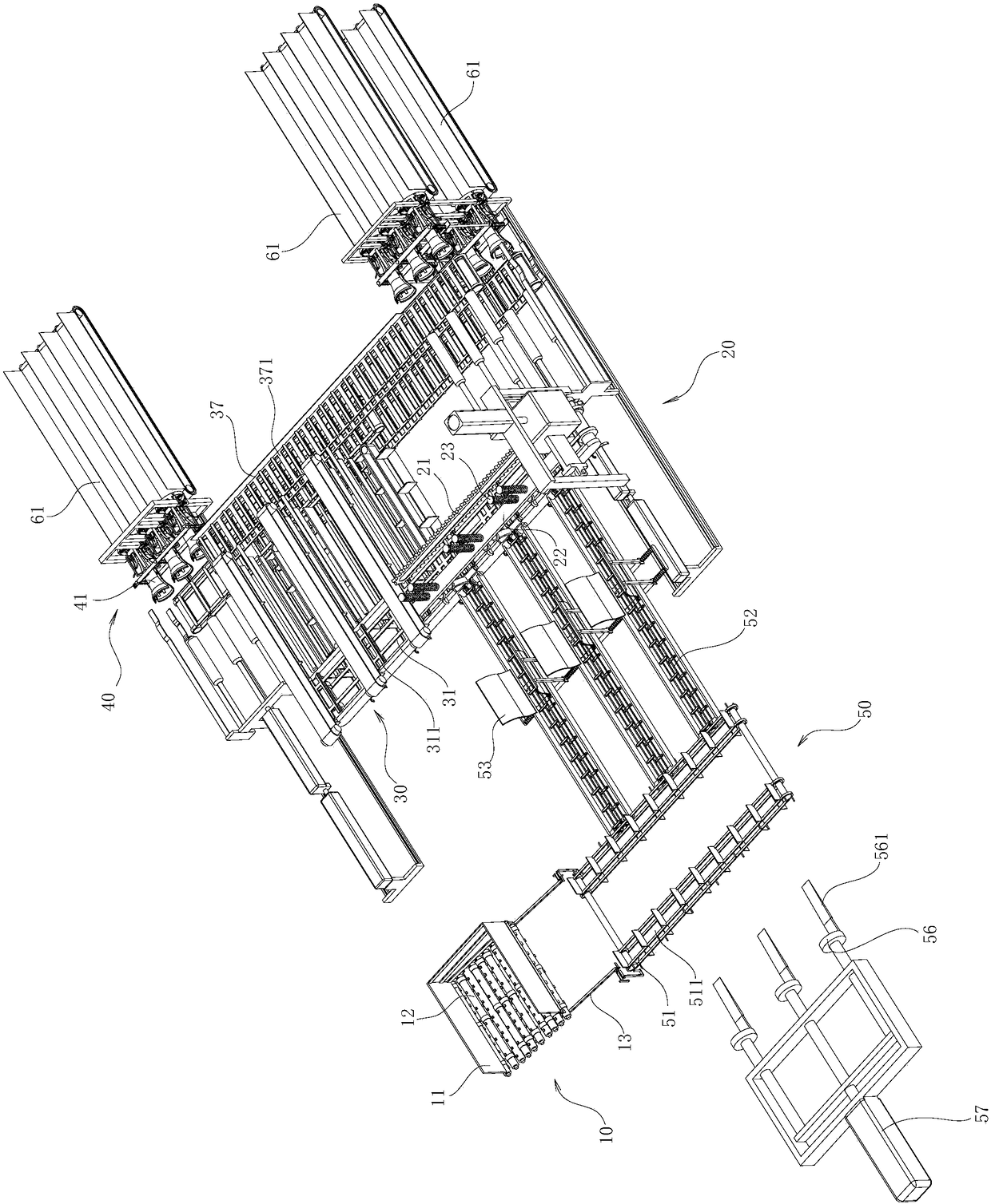
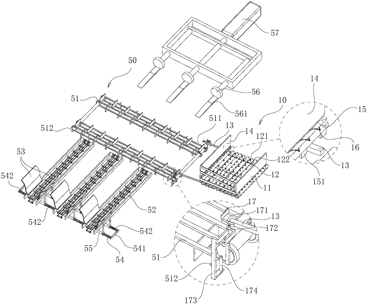
[0034] combine Figure 1 to Figure 32 , the present invention is further described:
[0035] In order to make the objects and advantages of the present invention clearer, the present invention will be described in detail below in conjunction with the examples. It should be understood that the following words are only used to describe one or several specific implementation modes of the present invention, and do not strictly limit the protection scope of the specific claims of the present invention.
[0036] As used herein, the terms "parallel" and "perpendicular" are not limited to their strict geometric definitions, but include reasonable and inconsistent tolerances for machining or human error.
[0037] The specific features of the planting base wood processing system for Chinese herbal medicines are described in detail below:
[0038] The base wood processing system for planting Chinese herbal medicines includes a log feeding device 10, the log feeding mechanism 10 horizon...
PUM
 Abstract
Description
Claims
Application Information
PatSnap Eureka turns technology decisions into work you can execute. Powered by our Innovation Knowledge Graph, it runs expert workflows across engineering, life sciences, materials and intellectual property. Get your review-ready output in minutes.


