
Aircraft

An aircraft and fuselage technology applied to aircraft. In this field, it can solve the problems of the wing paying a huge structural weight cost, low endurance, and the installation structure of separate power equipment.

Pending Publication Date: 2019-01-04
深圳筋斗云智能科技有限公司
View PDF6 Cites 7 Cited by
  • Summary
  • Abstract
  • Description
  • Claims
  • Application Information

AI Technical Summary

Problems solved by technology

At present, the most representative tiltrotor aircraft in the world is the V22 "Osprey". Its endurance can reach nearly 10 times that of ordinary helicopters, but its rotor system overload capacity is only 1.4, far less than 3.5 of helicopters. Therefore, the maneuverability Poor; in addition, the V22's engine and rotor tilt system components are mounted on the wingtips, requiring the wing to pay a huge structural weight penalty
Miniature / light tilt-rotor aircraft with four rotors have begun to appear in China, and the flight stability has been improved in theory, but it is only a mechanical combination of multi-rotor aircraft and fixed-wing aircraft, requiring a separate power equipment installation structure
Moreover, in the fixed-wing cruising state, if the four power units work at the same time, a pitch-variable structure is required to ensure the high efficiency of the four power plants. A power plant stops working and becomes a "dead weight", so the endurance is low

Method used


Image

  • Aircraft
  • Aircraft
  • Aircraft

Examples


Embodiment Construction

[0038] The following will clearly and completely describe the technical solutions in the embodiments of the present invention with reference to the accompanying drawings in the embodiments of the present invention. Obviously, the described embodiments are only some, not all, embodiments of the present invention. Based on the embodiments of the present invention, all other embodiments obtained by those skilled in the art without creative efforts fall within the protection scope of the present invention.

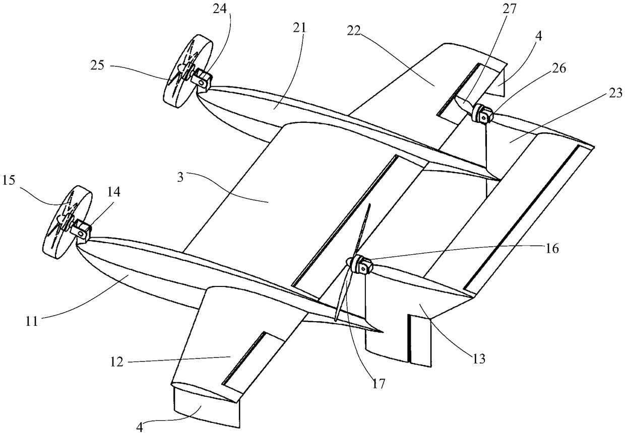
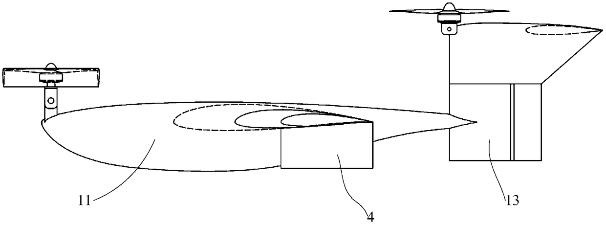
[0039] Such as figure 1 As shown, the embodiment of the present invention provides an aircraft. The aircraft in the embodiment of the present invention may be, for example, an unmanned aircraft, such as a Class C ground-effect aircraft capable of vertical take-off and landing.

[0040] In the embodiment of the present invention, the aircraft includes a left fuselage 11 , a right fuselage 21 , and a center wing 3 arranged between the left fuselage 11 and the right fuselage 21 ...


PUM


Abstract

The embodiment of the invention discloses an aircraft, which can be used for switching flight mode. The aircraft of the embodiment of the invention comprises a left fuselage, a right fuselageand a middle wing, one side of the left fuselageis provided with a left wing, the tail part of the left fuselageis provided with a left vertical tail, the left fuselage is equipped with a left forward power tilt driving device, the left forward power tilt driving device is equipped with a left front power tilt driving device, a left rear power tilting driving device is arranged on the left vertical tail, and a left rear power device is arranged on the left rear power tilting driving device; one side of the right fuselage is provided with a right wing, the tail part of the right fuselageis provided witha right vertical tail, a right front power tilting driving device is arranged on the right fuselage, a right front power device is arranged on the right front power tilting driving device, a right rear power tilting driving device is arranged on the right vertical tail, a right rear power device is arranged on the right rear power tilting driving device; the power tilting driving device is used for driving the power device tilt. In this way, the aircraft has a variety of available flight modes to achieve a switching of the flight mode during use.

Description

technical field [0001] The invention relates to the field of flying equipment, in particular to an aircraft. Background technique [0002] There are many types of aircraft, such as ground-effect aircraft, tilt-rotor aircraft, etc., and different types of aircraft have different characteristics. [0003] For example, a ground-effect aircraft is an aircraft that uses the wing-ground effect to fly. The ground effect aircraft has the following advantages: (1) When the aircraft flies close to the water surface, ice surface or flat land surface (collectively referred to as the support surface), a high-pressure air cushion is formed between the wings of the aircraft and the support surface, which can greatly increase the lift and drag of the aircraft Ratio (increased lift coefficient, reduced induced drag), so that the aircraft has higher aerodynamic efficiency and greater load capacity; (2) Ground-effect aircraft can fly at very low altitudes, so it also has higher flight safety ...

Claims


Application Information

Patent Timeline
IPC IPC(8): B64C27/26B64C27/28B64C29/00
CPCB64C27/26B64C27/28B64C29/0033B64U10/25B64U30/20B64U50/13B64U10/10
Inventor 饶大林
Owner 深圳筋斗云智能科技有限公司
Learn More