Hydraulic axial plunger type transmission roller capable of adjusting speed

A transmission roller and axial column technology, which is applied in the field of hydraulic axial plunger transmission rollers and belt conveyor transmission rollers, can solve the problems of complicated installation and debugging, increased production costs, and increased maintenance costs of supporting facilities, and achieves The effect of reducing production costs and facilitating installation and maintenance

Inactive Publication Date: 2019-01-04
XUZHOU UNIV OF TECH
View PDF0 Cites 1 Cited by
  • Summary
  • Abstract
  • Description
  • Claims
  • Application Information

AI Technical Summary

Problems solved by technology

This traditional belt conveyor transmission needs to be installed on the side of the drive roller. For heavy-duty belt conveyors such as mine belt conveyors, the huge drive motor and reducer not only need to occupy additional installation space, but also for space The narrow coal mine underground coal transport roadway needs additional excavation of the installation and maintenance space of the transmission device, and it is necessary to ensure the coaxial installation of the reducer output shaft and the transmission drum during the installation process, and the installation and debugging are more complicated; in addition, due to the explosion-proof Particularity, the drive motors used in traditional mining belt conveyor transmissions need to use explosion-proof motors, which not only increases the production cost, but also increases the maintenance cost of supporting facilities (the use of high-power explosion-proof motors requires higher voltage grade)

Method used


Image

  • Hydraulic axial plunger type transmission roller capable of adjusting speed
  • Hydraulic axial plunger type transmission roller capable of adjusting speed
  • Hydraulic axial plunger type transmission roller capable of adjusting speed

Examples


Embodiment Construction

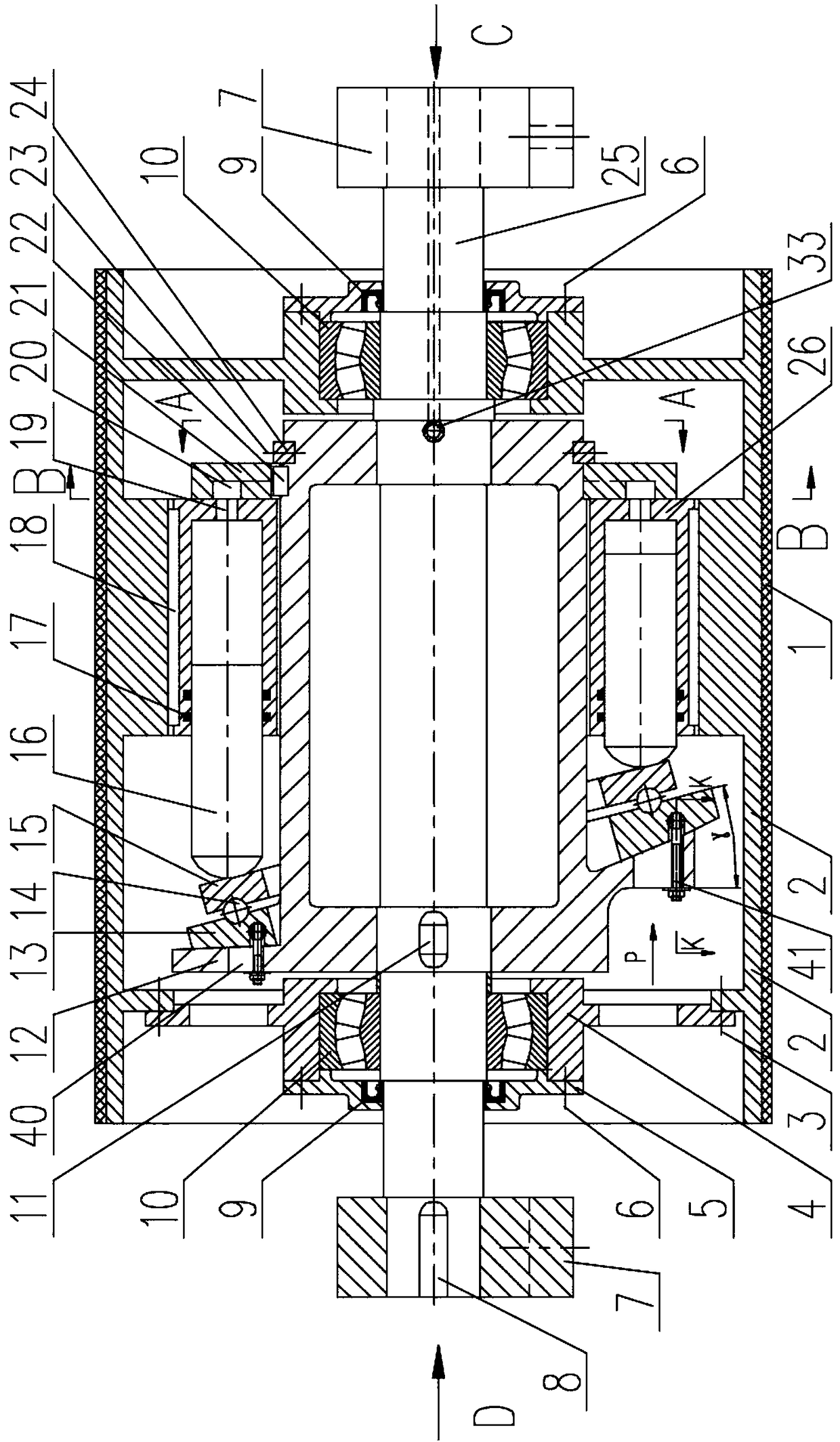
[0031] Below in conjunction with accompanying drawing, the present invention will be further described (hereinafter referred to as figure 1 The direction to the right of the front is described as the front).

[0032] Such as figure 1As shown, the speed-adjustable hydraulic axial plunger type transmission drum includes a cylinder body 2, a web plate 4, and a drum shaft 25; the outer surface of the cylinder body 2 is covered with a rubber layer 1, and two web plates 4 are fixed symmetrically front and back. Inside the cylinder body 2, at least one web plate 4 is fixedly installed in the interior of the cylinder body 2 through the web plate mounting bolts 3. The center position of the web plate 4 is provided with a bearing seat structure, and the bearing seat structure is provided with a bearing 10 inside and outside A bearing end cover 5 is provided, and a dust-proof seal 9 is also provided inside the bearing end cover 5. The bearing end cover 5 is fixedly installed on the radi...


PUM


Abstract

The invention discloses a hydraulic axial plunger type transmission roller capable of adjusting speed. The hydraulic axial plunger type transmission roller capable of adjusting speed comprises a roller driving device arranged between two radial plates, the roller driving device comprises a supporting body, a steel ball, an inclined disc, a rotary table, a plunger, a cylinder body and an oil distribution disc, and a shaft oil inlet and a shaft oil outlet are formed in the front end surface of a roller shaft. According to the hydraulic axial plunger type transmission roller capable of adjustingspeed, rotary torque is generated on the rotary table by using radial component force of the rotary table generating counter-acting force on the plunger under the extrusion of the plunger, the rotarytorque pushes the barrel body to rotate through cylinder bodies mounted on the inner surface of barrel body in a uniform distribution mode in the circumferential direction, on the one hand, the innerspace of the barrel body can be fully used, on the other hand, a mode of roller axial inlet and outlet pressure oil is adopted, therefore, additional transmission device installation space does not need to be arranged, installation and maintenance are facilitated, the production cost and the maintenance cost of auxiliary facility can be reduced, and the hydraulic axial plunger type transmission roller capable of adjusting speed is especially suitable for high gas mines or belt conveyors with no space arranged in a transmission device.

Description

technical field [0001] The invention relates to a drive roller for a belt conveyor, in particular to a speed-adjustable hydraulic axial plunger drive roller suitable for belt conveyors in underground mines, on the ground, in ports, etc. The field of conveyor technology. Background technique [0002] Belt conveyors, also known as belt conveyors, are widely used in various industries such as machinery, electronics, tobacco, injection molding, post and telecommunications, printing, and food. Belt conveyors can be divided into heavy belt conveyors such as mining belt conveyors according to their conveying capacity, and light belt conveyors such as those used in electronic plastics, food light industry, chemical and pharmaceutical industries. Belt conveyor is a kind of machinery that is driven by friction to transport materials in a continuous manner. It is mainly composed of frame, conveyor belt, idler roller, roller, tensioning device, transmission device, etc. A material con...

Claims


Application Information

Patent Timeline
Patent Type & Authority Applications(China)
IPC IPC(8): B65G23/04
CPCB65G23/04
Inventor 陆兴华
Owner XUZHOU UNIV OF TECH
Why Eureka
Try Eureka