Cyclone type inflow control valve
A technology of inflow control valve and swirl chamber, which is applied in the direction of production fluid, wellbore/well valve device, wellbore/well components, etc. problems, to achieve the effect of improving oil recovery, prolonging oil production time, and improving reliability
- Summary
- Abstract
- Description
- Claims
- Application Information
AI Technical Summary
Problems solved by technology
Method used
Image
Examples
Embodiment 1
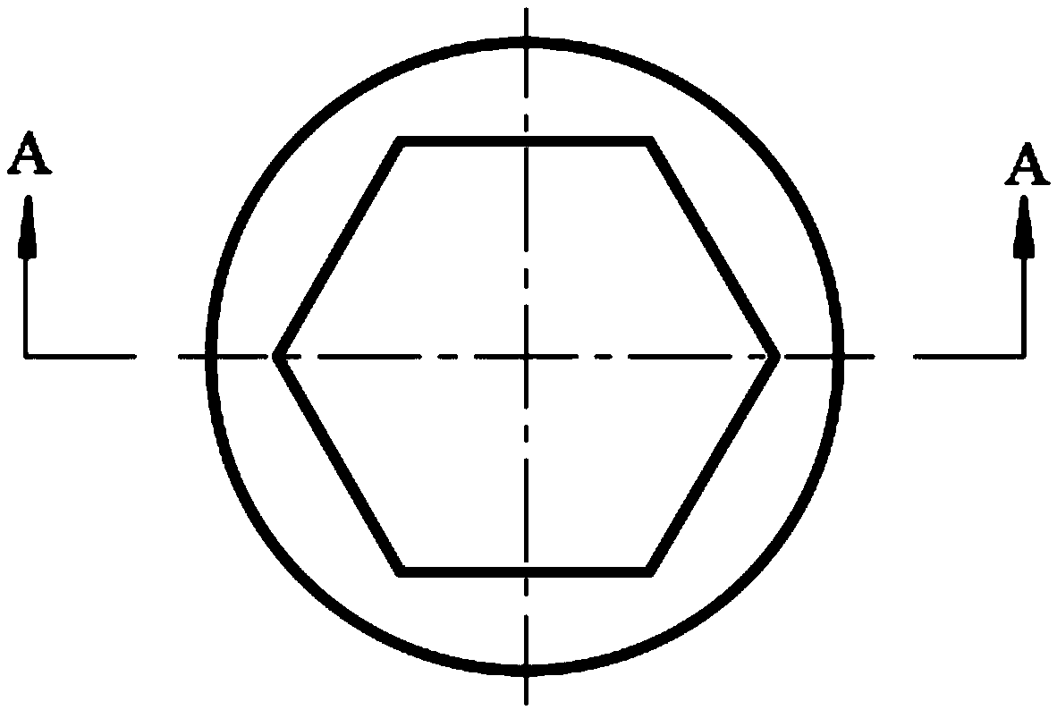
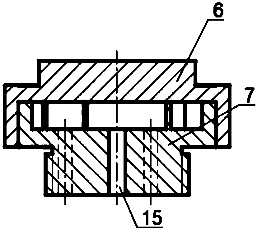
[0029] Such as Figure 2-Figure 4 As shown, the restrictor valve 4 includes an end cover 6 and a base 7, the base 7 is provided with a liquid inlet 8 and an annular flow channel 9 communicating with the liquid inlet 8, the annular flow channel 9 is arc-shaped, Thus, the fluid guided into the annular flow channel 9 flows in an arc-shaped trajectory, and is located in the circular cavity surrounded by the annular flow channel 9, and a swirl chamber 12B and a plurality of swirl chambers 10A are distributed along the circumferential direction. The guide flow channel 11 of the cyclone chamber 12B is located in the annular flow channel, and the opening direction of the guide flow channel 11 is the same as the flow direction of the fluid in the annular flow channel 9 here, that is, the flow direction of the guide flow channel 11 and the fluid in the annular flow channel 9 The flow direction is the same, the fluid in the annular flow channel 9 enters the guide flow channel 11 tangenti...
Embodiment 2
[0034] Such as Figure 5 As shown, the base 7 of the restrictor valve 4 is provided with a liquid inlet 8 and an annular flow channel 9 communicating with the liquid inlet 8. The annular flow channel 9 is arc-shaped, thereby guiding the The fluid flows in an arc-shaped trajectory, located in the circular cavity surrounded by the annular flow channel 9, and a plurality of swirl chambers A10 are distributed along the circumference, and the swirl chamber A10 contains fluid with tangential flow For spiral flow, the guiding flow channel 11 of the cyclone chamber A10 is connected to the circular flow channel 9, and the opening direction of the guiding channel 11 is the same as the flow direction of the fluid in the circular flow channel 9, that is, the guiding channel 11 is connected to the annular flow channel. The flow direction of the fluid in the channel 9 is the same, the fluid in the annular flow channel 9 enters the guide splitter groove 11 tangentially, the liquid inlet 8, t...
Embodiment 3
[0038] The swirl type inflow control valve of embodiment 1 works in the production well as follows:
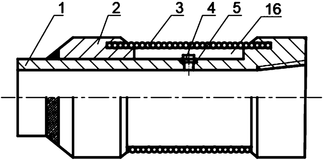
[0039] The reservoir fluid flows into the control chamber 16 after filtering the sand through the screen tube 3, and then enters the annular flow channel 9 through the liquid inlet 8 of the restrictor valve 4 in the control chamber 16, and part of the fluid passes through the nozzle A14 in the cyclone chamber A10 After throttling, it flows into the base pipe 1, and another part of the fluid is pre-selected by the annular flow channel 9, and then enters the swirl chamber B12 from the guide flow channel 11, and performs a spiral movement in the swirl chamber 12B, and finally is throttled by the nozzle B15 Flow into base pipe 1.
[0040] 1. When the fluid is pure oil, after the oil enters the restrictor valve 4 from the liquid inlet 8, due to the high viscosity of the oil, the viscous force is much greater than the inertial force, and tends to flow out of the restrictor valve 4 a...
PUM
 Abstract
Description
Claims
Application Information
 - R&D
- Intellectual Property
- Life Sciences
- Materials
- Tech Scout
- Unparalleled Data Quality
- Higher Quality Content
- 60% Fewer Hallucinations
Browse by: Latest US Patents, China's latest patents, Technical Efficacy Thesaurus, Application Domain, Technology Topic, Popular Technical Reports.
© 2025 PatSnap. All rights reserved.Legal|Privacy policy|Modern Slavery Act Transparency Statement|Sitemap|About US| Contact US: help@patsnap.com


