Novel regenerator and pulse pipe refrigerator adopting regenerator structure
A pulse tube refrigerator and regenerator technology, applied in refrigerators, gas cycle refrigerators, superheaters, etc., can solve problems such as structural defects of regenerators, and reduce the low efficiency of regenerators and reduce airflow. Non-uniformity, the effect of reducing uneven flow
- Summary
- Abstract
- Description
- Claims
- Application Information
AI Technical Summary
Problems solved by technology
Method used
Image
Examples
Embodiment 1
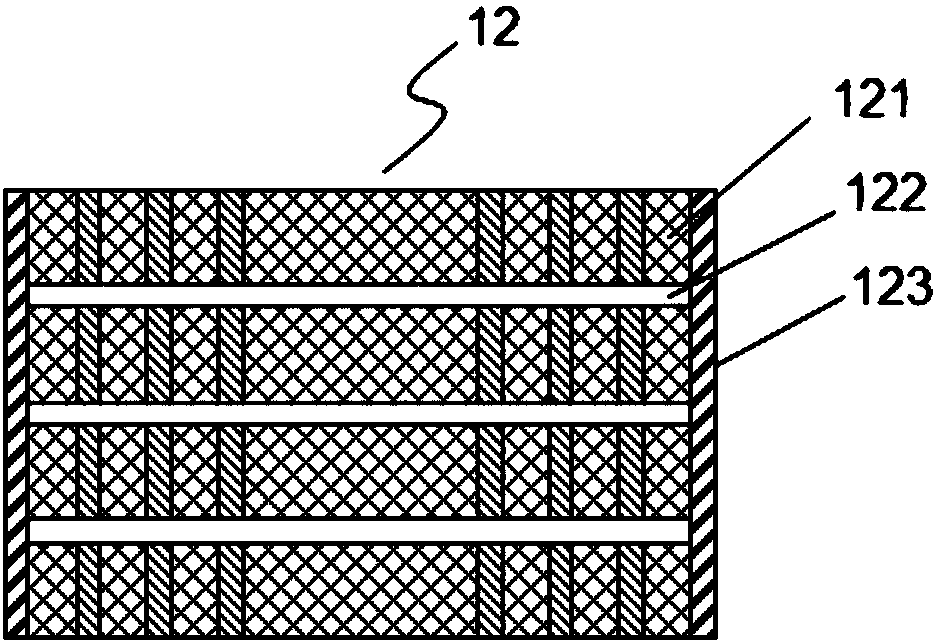
[0029] A new type of regenerator, refer to figure 1 , figure 2 As shown, it consists of a regenerator tube 123 and a plurality of spaced regenerator packing units 121 packed in the regenerator tube 123, and there is a gap 122 between two adjacent regenerator packing units 121, and the regenerator Heater filler unit 121 is composed of filler 1211 and separators 1212 , separators 1212 are arranged at intervals, fillers 1211 are filled between adjacent separators 1212 , fillers 1211 are arranged between separators 1212 and regenerator tubes 123 . The regenerator filling units 121 are arranged at intervals along the length direction of the regenerator tube 123 , and the fillers 1211 are distributed at intervals along the radial direction of the regenerator tube 123 .
[0030] The partition can be constructed in two ways:
[0031] The first structure is: the partition 1212 is a plurality of annular plates or annular tubes of different diameters coaxially sleeved, the filler 1211...
Embodiment 2
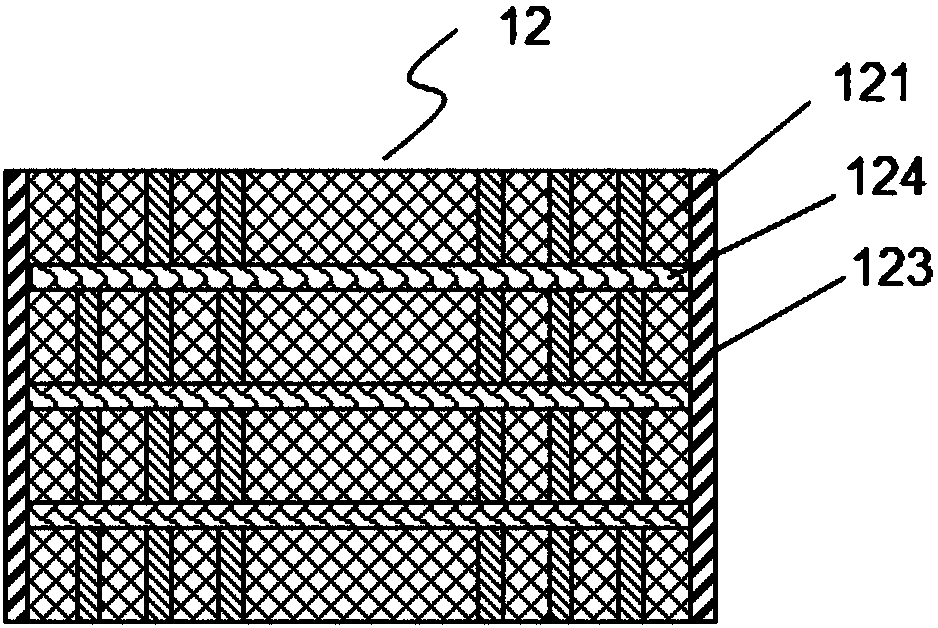
[0036] A new type of regenerator, refer to figure 1 , image 3 , consisting of a regenerator tube 123 and a plurality of regenerator packing units 121 arranged at intervals filled in the regenerator tube 123, a porous material 124 is arranged between two adjacent regenerator packing units 121, and the regenerator The filler unit 121 is composed of fillers 1211 and separators 1212 , the separators 1212 are arranged at intervals, the fillers 1211 are filled between adjacent separators 1212 , and the fillers 1211 are arranged between the separators 1212 and the regenerator tubes 123 . The regenerator filling units 121 are arranged at intervals along the length direction of the regenerator tube 123 , and the fillers 1211 are distributed at intervals along the radial direction of the regenerator tube 123 .
[0037] The partition can be constructed in two ways:
[0038] The first structure is: the partition 1212 is a plurality of annular plates or annular tubes of different diamet...
Embodiment 3
[0043] A new type of regenerator, refer to Figure 4 , Figure 5 As shown, in this embodiment, the regenerator is a hollow structure. Specifically, the new regenerator of this embodiment is composed of a regenerator tube 123 and a plurality of spaced regenerator filling units 121 filled in the regenerator tube 123, and two adjacent regenerator filling units There is a gap 122 between 121, and the regenerator filling unit 121 is composed of a filler 1211 and a partition 1212. The partitions 1212 are arranged at intervals, and the filler 1211 is filled between adjacent partitions 1212. There are fillers 1211 therebetween. The regenerator filling units 121 are arranged at intervals along the length direction of the regenerator tube 123 , and the fillers 1211 are distributed at intervals along the radial direction of the regenerator tube 123 .
[0044] In this embodiment, the regenerator filling unit 121 is provided with a hollow portion for placing the vessel 14 , and the rege...
PUM
 Abstract
Description
Claims
Application Information
 - R&D
- Intellectual Property
- Life Sciences
- Materials
- Tech Scout
- Unparalleled Data Quality
- Higher Quality Content
- 60% Fewer Hallucinations
Browse by: Latest US Patents, China's latest patents, Technical Efficacy Thesaurus, Application Domain, Technology Topic, Popular Technical Reports.
© 2025 PatSnap. All rights reserved.Legal|Privacy policy|Modern Slavery Act Transparency Statement|Sitemap|About US| Contact US: help@patsnap.com


