
Method and apparatus for using solar energy to enhance the operation of a compressed air energy storage system

a technology of compressed air energy storage and solar energy, which is applied in the direction of wind energy generation, mechanical energy handling, power supply for propulsion, etc., can solve the problems of not being a highly reliable source of energy, not always available energy when the energy is needed, and the extent to which sun energy can be provided is not always predictable, so as to enhance the efficiency of compressed air energy storage and enhance the efficiency of solar energy generated. , to achieve the effect of enhancing the efficiency of the compressed air energy storag

Inactive Publication Date: 2011-09-27
ENIS BEN M +1
View PDF10 Cites 3 Cited by
  • Summary
  • Abstract
  • Description
  • Claims
  • Application Information

AI Technical Summary

Benefits of technology

"The present invention is an improvement over previous attempts to use solar energy to enhance the efficiency of compressed air energy storage systems. It incorporates the benefits of both methods, by using a photovoltaic cell panel to collect solar energy and convert it into electrical energy, which can be used to drive a compressor to produce compressed air energy. This energy can then be stored in a high pressure storage tank, where it helps to maintain the temperature of the compressed air. The system also uses the heated water to generate electrical power, which can be used to power a generator set or a combined heat and power system. The design of the storage tank also helps to improve efficiency, with an inner pressure vessel and an outer wall that are concentrically oriented. Overall, the invention provides a more efficient and consistent system for generating and using solar energy to enhance the efficiency of compressed air energy storage."

Problems solved by technology

One problem associated with the use of renewable energy such as the sun and wind is that the energy is not always available when the energy is needed.
Solar power, for example, is only available during the day, and is most effective when the sun is shining brightly, and therefore, the extent to which energy can be provided by the sun is not always predictable.
Wind energy is also only available when the wind is blowing, and therefore, it is not a highly reliable source of energy.
Another drawback to these resources is that even when energy is available, the amount of energy that they generate is not always consistent.
For example, even when the wind blows, it does not always blow at the same speed, or at regular intervals, and therefore, the amount of energy that can be generated is not always consistent.
The same is true of solar energy, i.e., the degree to which the sun is shining and available can be sporadic; it often depends on the weather, and therefore, it is never certain how much energy can be generated at any given moment in time.
Nevertheless, one problem associated with time-shifting relates to the inherent inefficiencies that can result from having to store energy in one form, and then converting the energy into another form before it can be used.
In such case, the energy used from storage can often end up costing more than the energy that was stored.
These inefficiencies can significantly reduce the economic incentives that are needed to promote the installation of these potentially viable systems.
Moreover, while there has been a steady increase in the number of photovoltaic (PV) cell projects that have been initiated and developed in recent years, each of these projects has had a serious shortfall in electric power production particularly in the late afternoon and early evening when the power demand is high.

Method used


Image

  • Method and apparatus for using solar energy to enhance the operation of a compressed air energy storage system
  • Method and apparatus for using solar energy to enhance the operation of a compressed air energy storage system
  • Method and apparatus for using solar energy to enhance the operation of a compressed air energy storage system

Examples


Embodiment Construction

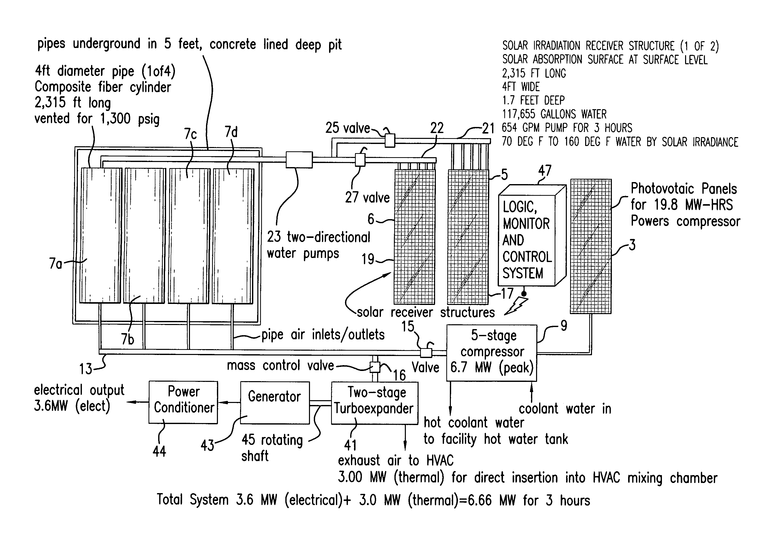
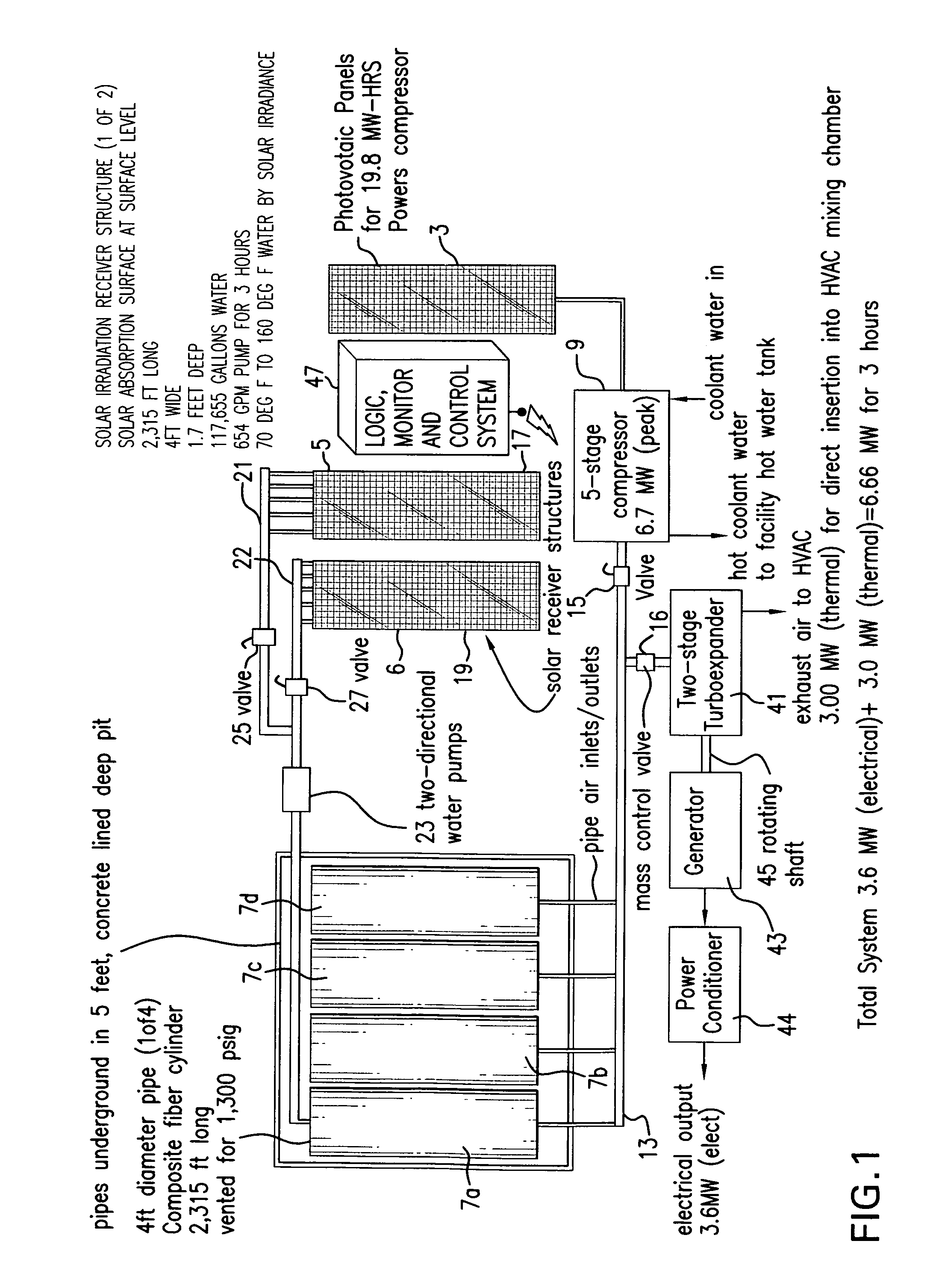
[0068]FIG. 1 shows the main components of the present system 1, including a photovoltaic cell panel 3, two solar receiving panels 5, 6, and several high pressure storage tanks 7a, 7b, 7c, and 7d, among other components.

[0069]Photovoltaic panel 3 is preferably capable of collecting solar photovoltaic energy from the sun's rays and converting it into electricity. Preferably, there are two different configurations that can be used in connection with the present system, including 1) highly transmissive photovoltaic solar cells, and 2) highly reflective photovoltaic solar cells. In either case, the solar cell will use a portion of the irradiated solar energy received by the panel for conversion to electricity, wherein the remainder is preferably either transmitted to a back-plate that conducts the energy away or reflected from the front surface to avoid overheating. The electricity produced by panel 3 can be used directly, such as when a large panel that can supply energy for immediate u...


PUM


Abstract

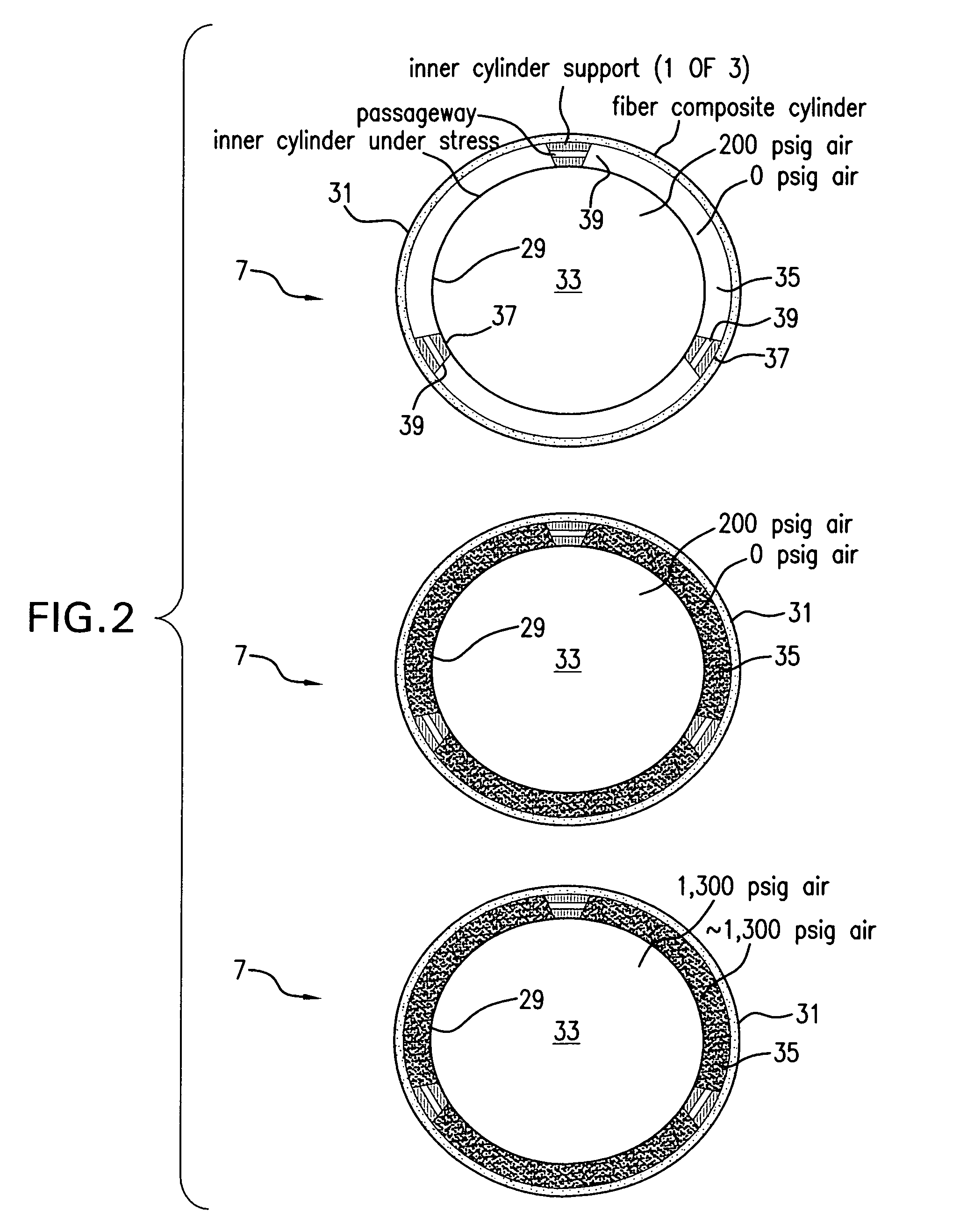
The invention relates to a method and apparatus for using solar energy to enhance the efficiency of a compressed air energy storage system (and visa-versa). The apparatus comprises a photovoltaic panel to drive a compressor, which provides compressed air energy into an inner vessel housed within a storage tank. Two solar receiving panels are used to heat water which can be circulated and stored within an annulus surrounding the inner vessel, wherein the heated water can help regulate the temperature of the compressed air within the tank. This way, when air is released using a turbo expander, any excess temperature drops that can otherwise result from air expansion can be avoided. The overall system efficiency is enhanced by the chilled air by-product of the turbo expander which is used to generate more electrical power from an associated fuel-driven generator set, and / or by the waste heat from the compressor and from the generator set exhaust which is used in a Combined Heat and Power system (CHP) to power either a steam-driven generator set or an absorption chiller.

Description

RELATED APPLICATIONS[0001]This application claims priority from U.S. Provisional Application Ser. Nos. 61 / 062,149, filed on Jan. 24, 2008, 61 / 068,170, filed on Mar. 5, 2008, and 61 / 195,418, filed on Oct. 7, 2008, all of which are incorporated herein by reference in their entirety.BACKGROUND OF THE INVENTION[0002]Due to the growing demand for energy throughout the world, concerns have grown about the future of the world's energy supplies. Not only are there limited supplies of oil and coal reserves available within the earth's crust, but due to the ongoing security problems and concerns that now exist throughout the world today, there has been a growing desire to reduce our nation's reliance on foreign oil.[0003]Indeed, many energy experts believe that a successful energy solution must include the ability to harness energy from what are often called natural renewable resources, such as the sun and wind. The renewability and abundant availability of these resources make them well suit...

Claims


Application Information

Patent Timeline
Patent Type & Authority Patents(United States)
IPC IPC(8): B60K16/00F01K1/00F03G6/00B60L8/00F01K3/00
CPCF02C1/02F03D9/007F03D9/028F03G6/001F24J2/0472F24J2/42F28D1/06F02C6/16Y02E70/30F03G6/003F24J2002/0092Y02E10/44Y02E10/465Y02E10/72Y02E20/14Y02E60/15F03D9/17F03D9/25F03D9/28F24S10/17F24S90/00F24S2020/17H02S10/12Y02A20/141Y02A20/142Y02E10/46Y02E10/50Y02E60/16Y02P80/15Y02T10/7072
Inventor ENIS, BEN M.LIEBERMAN, PAUL
Owner ENIS BEN M
Learn More