
Strain gauges, pressure sensors, and interventional medical catheters

A pressure sensor and strain gauge technology, which is applied in the field of medical devices, can solve the problems of application limitations, large strain gauge size, etc., and achieve the effect of saving wiring space, reducing size, and good measurement effect

Active Publication Date: 2020-04-10
SHANGHAI MICROPORT EP MEDTECH CO LTD
View PDF7 Cites 0 Cited by
  • Summary
  • Abstract
  • Description
  • Claims
  • Application Information

AI Technical Summary

Problems solved by technology

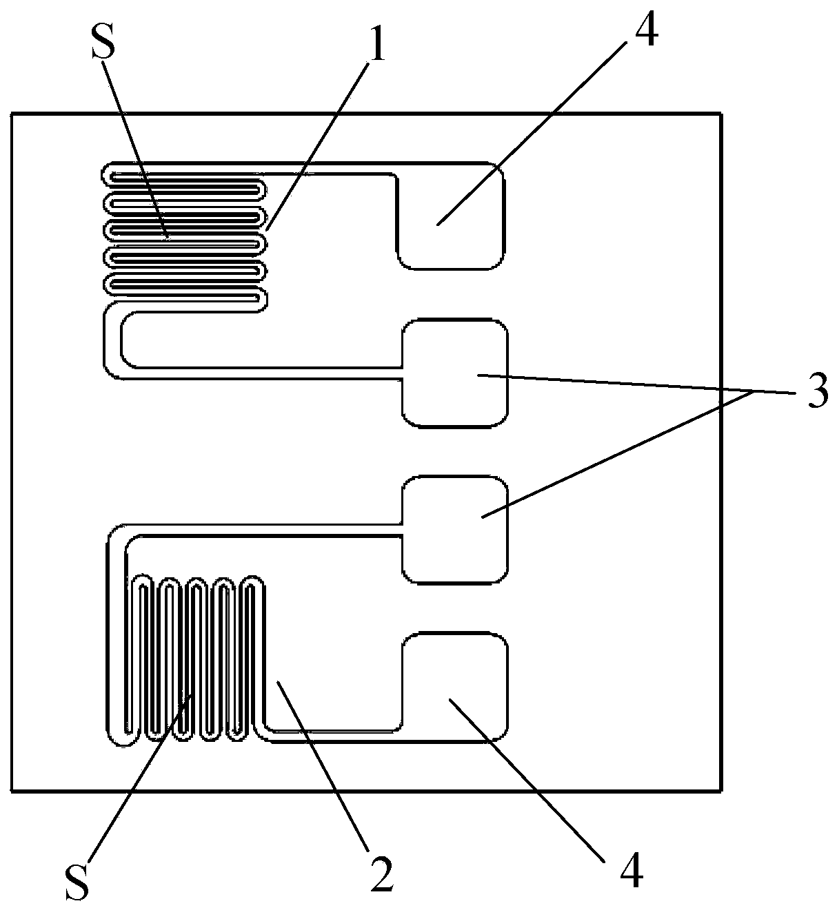
[0007] The purpose of the present invention is to provide a strain gauge, a pressure sensor and an interventional medical catheter, so as to solve the problem that the size of the strain gauge on the interventional medical catheter in the prior art is too large and the application is limited

Method used


Image

  • Strain gauges, pressure sensors, and interventional medical catheters
  • Strain gauges, pressure sensors, and interventional medical catheters
  • Strain gauges, pressure sensors, and interventional medical catheters

Examples


Embodiment 1

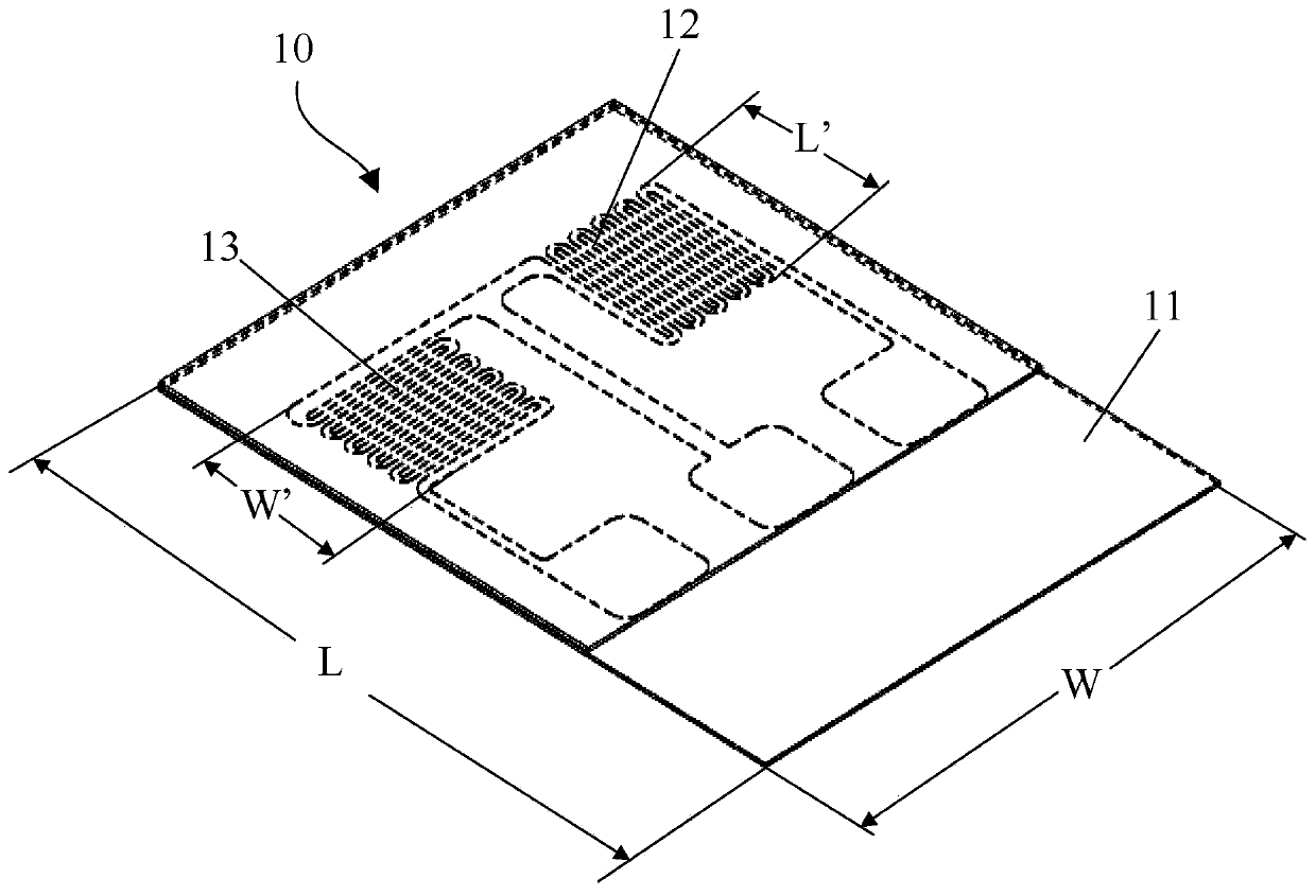
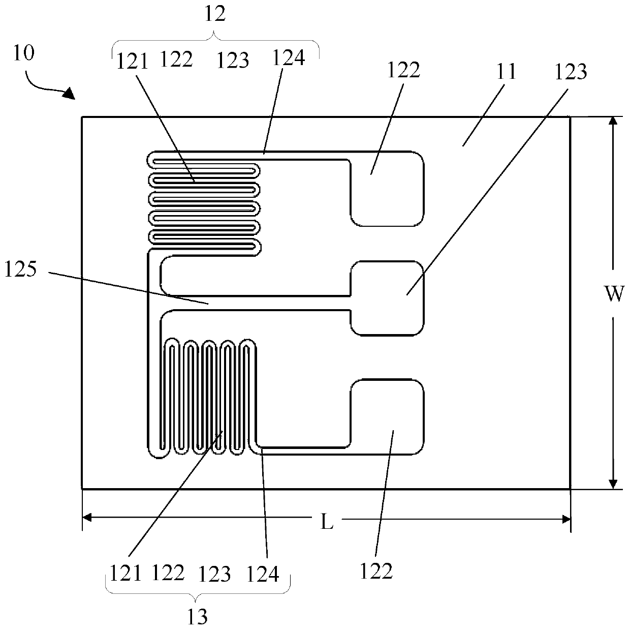
[0064] figure 2 is an isometric view of the strain gauge 10 provided in Embodiment 1 of the present invention, image 3 yes figure 2 A top view of the strain gauge 10 is shown. Such as figure 2 and image 3 As shown, the strain gauge 10 includes a base 11 and a vertical sensitive grid 12 and a horizontal sensitive grid 13 arranged on the base 11 . Here, the longitudinal sensitive grid 12 is usually arranged along the axial direction of the measured object (that is, the length L' of the longitudinal sensitive grid is parallel to the axial direction of the measured object, and the grid width W' of the longitudinal sensitive grid is parallel to the measured object The circumferential direction of the object), the transverse sensitive grid 13 is arranged along the direction perpendicular to the axial direction of the measured object (that is, the width W' of the transverse sensitive grid is parallel to the axial direction of the measured object, but the length L' of the tra...

Embodiment 2

[0101] The strain gauges and pressure sensors provided in this embodiment are basically the same as those in Embodiment 1, and only the differences will be described below.

[0102] In order to reduce the amount of strain gauges used on the elastic body, the inventors found that at least two longitudinal sensitive grids can be arranged on the same substrate, which can also meet the actual contact force measurement requirements. For the convenience of description, the technical solution of this embodiment will be further described by taking two vertical sensitive grids as an illustration.

[0103] In one approach, such as Figure 10 As shown, two vertical sensitive grids 12 aligned side by side are arranged at intervals along the width direction of the substrate, and the installation direction of the two vertical sensitive grids 12 is parallel to the length direction of the substrate (that is, where the grid length L' of the vertical sensitive grid 12 is located) direction par...


PUM

PropertyMeasurementUnit
lengthaaaaaaaaaa
electrical resistanceaaaaaaaaaa
gauge factoraaaaaaaaaa

Abstract

The invention provides a strain gauge, a pressure sensor and an intervention medical catheter. The strain gauge includes a base and at least two sensitive grids arranged on the base, the at least two sensitive grids are arranged along two mutually perpendicular directions and share a ground port. The pressure sensor includes an elastic body and strain gauges arranged on the elastic body. The interventional medical catheter includes a distal end of the catheter and a pressure sensor arranged at the distal end of the catheter. On the one hand, the present invention saves the wiring space when the strain gauge is installed and used on the interventional medical catheter, facilitates the smooth installation and use of the strain gauge on the interventional medical catheter, improves the adaptability of the strain gauge, and reduces the strain on the other hand. The size of the sheet, thereby shortening the length of the elastic body of the pressure sensor, and reducing the size of the interventional medical catheter at the same time.

Description

technical field [0001] The invention relates to the technical field of medical instruments, in particular to a strain gauge, a pressure sensor and an interventional medical catheter. Background technique [0002] For cardiac radiofrequency ablation catheters, strain gauges are usually arranged on them to measure the contact force between the distal end of the catheter and the tissue or vessel wall, so as to accurately monitor the implementation process of the ablation treatment, thereby ensuring the success rate of the operation. Due to the advantages of low price, fast response, large measurement range and stable performance, strain gauges have been widely used in the field of interventional medicine. [0003] Generally, strain gauges are made by pasting metal sensitive grids on a plastic base film. The metal sensitive grid is a group of parallel wires formed by a narrow conductor zigzag arrangement. When it is stretched, the sensitive grid becomes narrower and longer, and...

Claims


Application Information

Patent Timeline
Patent Type & Authority Patents(China)
IPC IPC(8): G01L1/22A61M25/00
CPCA61M25/00G01L1/2287A61M2025/0002A61B18/12G01B7/16G01L1/22G01B7/20A61B90/06A61B2090/065A61B18/1492A61B2562/0261A61B2562/046A61B2562/164
Inventor 沈磊苗涛梁波王妹王慧孙毅勇
Owner SHANGHAI MICROPORT EP MEDTECH CO LTD
Learn More