Field flow fractionation device

A technology of field flow separation and side separation, which is applied in wet separation, material separation, solid separation, etc., can solve the problems of long time and poor efficiency, and achieve the effect of increasing analysis efficiency, suppressing device composition and cost

Active Publication Date: 2019-01-04
SHIMADZU SEISAKUSHO CO LTD
View PDF10 Cites 4 Cited by
  • Summary
  • Abstract
  • Description
  • Claims
  • Application Information

AI Technical Summary

Problems solved by technology

Therefore, the sequential analysis using one field flow separation device has the following problems: the efficiency is poor, and it takes a long time when analyzing a plurality of samples

Method used


Image

  • Field flow fractionation device
  • Field flow fractionation device
  • Field flow fractionation device

Examples


Embodiment Construction

[0026] Hereinafter, an embodiment of the field flow separation device will be described with reference to the drawings.

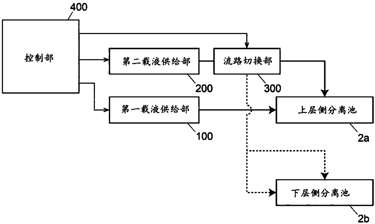
[0027] use figure 1 , the schematic configuration of the field-flow separation device of this embodiment will be described.

[0028] The field flow separation device of this embodiment includes an upper separation cell 2 a , a lower separation cell 2 b , a first carrier liquid supply unit 100 , a second carrier liquid supply unit 200 , a channel switching unit 300 and a control unit 400 . The upper-layer-side separation tank 2a and the lower-layer-side separation tank 2b form a pair of separation tanks. The field flow separation device includes a separation cell group consisting of a plurality of separation cells including at least these separation cell pairs 2a, 2b.

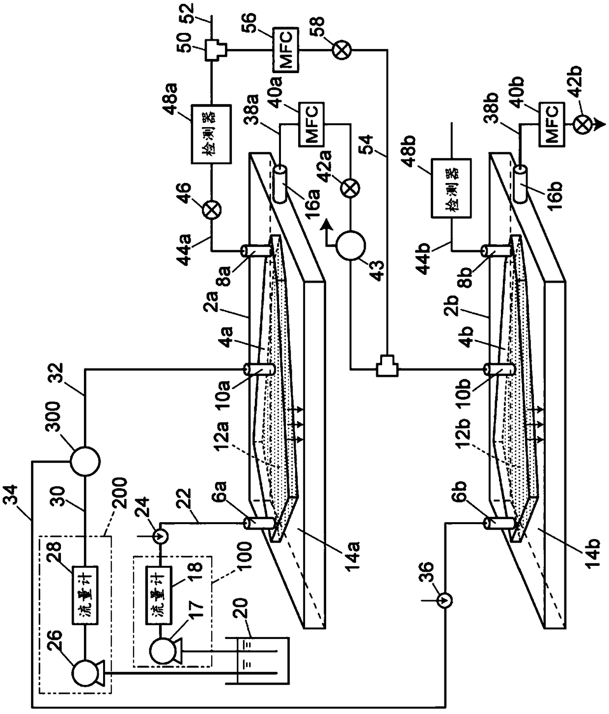
[0029] Although figure 1 It is not shown in the figure, but both the upper layer side separation cell 2a and the lower layer side separation cell 2b have: a separation channel for separati...


PUM

PropertyMeasurementUnit
particle diameteraaaaaaaaaa

Abstract

This field flow fractionation device is provided with a flow path switching unit which switches and connects a second carrier fluid supply unit to one port among a second inlet port of an upper end-side separation cell, an inlet port of a lower end-side separation cell, or a second inlet port of a lower end-side separation cell. In addition, the field flow fractionation device is configured such that: when focusing is performed to generates a carrier fluid flow against the carrier fluid flow from the inlet port in the upper end-side separation cell, the second carrier fluid supply unit is connected to the second inlet port of the upper end-side separation cell, and when the focusing in the upper end-side separation cell is completed, the second carrier fluid supply unit is connected to theinlet port or the second inlet port of the lower end-side separation cell.

Description

technical field [0001] The invention relates to a field flow separation device for separating and dividing microparticles contained in a fluid by field flow separation. Background technique [0002] As a method for separating, detecting or classifying fine particles dispersed in a solution in a wide range of particle diameters ranging from 1 nm to 50 μm, so-called cross-flow type field flow separation is conventionally known (for example, refer to Patent Document 1). [0003] A cross-flow field flow separation device adopting an asymmetric channel structure has a separation channel for separating samples. One of the walls forming the separation channel is a semipermeable membrane (also called a separation membrane) with pores such as RC (regenerated cellulose) or PES (polyethersulfone), and furthermore, a device called It is a porous flat plate of glass frit. The carrier liquid introduced into the channel passes through the wall surface, thereby generating a vertical flow ...

Claims


Application Information

Patent Timeline
Patent Type & Authority Applications(China)
IPC IPC(8): B03B5/62B03B5/00G01N15/00
CPCG01N30/0005G01N15/00G01N2030/003G01N30/38G01N30/466B03B5/62
Inventor 老川幸夫堀池重吉中矢麻衣子叶井正树
Owner SHIMADZU SEISAKUSHO CO LTD
Why Eureka
Try Eureka