
Turbine device

A turbine and control device technology, applied in the field of turbine devices, can solve the problems of poor stirring effect and low stirring efficiency, and achieve the effect of convenient operation and simple structure

Inactive Publication Date: 2019-01-08
童钟益
View PDF0 Cites 0 Cited by
  • Summary
  • Abstract
  • Description
  • Claims
  • Application Information

AI Technical Summary

Problems solved by technology

[0002] In modern industry, many devices use turbine devices as power, which can make greater use of energy. At the same time, stirring is a necessary process in many industries, but basically it uses simple one-way stirring, stirring The efficiency is low, and the stirring effect is poor at the same time. Therefore, continue to use a turbine device that can automatically switch the stirring direction. Stir more fully

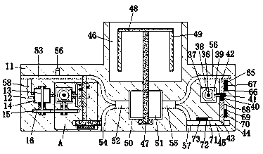
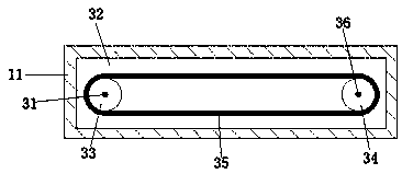
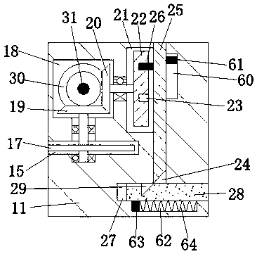
Method used


Image

  • Turbine device
  • Turbine device
  • Turbine device

Examples


Embodiment Construction

[0013] Combine below Figure 1-4 The present invention will be described in detail.

[0014] refer to Figure 1-4, a turbine device according to an embodiment of the present invention, comprising a first device body 11, a control device disposed in the first device body 11, and a stirring device disposed in the first device body 11, the The control device includes a first turbine chamber 12 arranged in the first device main body 11, a first rotating shaft 13 is rotatably arranged in the first turbine chamber 12, and arrayed and fixedly arranged on the first rotating shaft 13 are The first turbine blade 14, the first transmission cavity 15 is arranged in the inner wall of the lower side of the first turbine cavity 12, the lower end of the first rotating shaft 13 extends into the first transmission cavity 15 and is fixedly connected with a first straight Gear 16, the right end of the first spur gear 16 is meshed with a second spur gear 17, the upper side of the second spur gea...


PUM


Abstract

The invention discloses a turbine device. The turbine device comprises a first device body, a control device arranged in the first device body, and a stirring device arranged in the first device body,wherein the control device comprises a first turbine cavity arranged in the first device body; a first rotating shaft is rotationally arranged in the first turbine cavity; a first turbine blade is fixedly arranged on the first rotating shaft in an array manner; a first transmission cavity is arranged on the inner wall of the lower side of the first turbine cavity; the lower end of the first rotating shaft extends into the first transmission cavity and is fixedly connected with a first straight gear; a second straight gear is meshed with the right end of the first straight gear; and a second transmission cavity is formed in the upper side of the second straight gear and in the inner wall of the upper side of the first transmission cavity. The turbine device takes a turbine as power to perform stirring, meanwhile can realize automatic switching of positive and negative rotation, realizes positive and negative rotation stirring, and ensures uniform stirring.

Description

technical field [0001] The invention relates to the technical field of industrial processing, in particular to a turbine device. Background technique [0002] In modern industry, many devices use turbine devices as power, which can make greater use of energy. At the same time, stirring is a necessary process in many industries, but basically it uses simple one-way stirring, stirring The efficiency is low, and the stirring effect is poor at the same time. Therefore, continue to use a turbine device that can automatically switch the stirring direction. Stir more thoroughly. Contents of the invention [0003] The object of the present invention is to provide a turbine device for overcoming the above-mentioned drawbacks in the prior art. [0004] A turbine device according to the present invention includes a first device body, a control device disposed in the first device body, and a stirring device disposed in the first device body, the control device includes a control dev...

Claims


Application Information

Patent Timeline
Patent Type & Authority Applications(China)
IPC IPC(8): B01F7/18B01F15/00
CPCB01F27/90B01F35/32065B01F35/332
Inventor 童钟益
Owner 童钟益
Learn More