A PC mainframe dust removal box with good dust removal effect

A technology for a dust box and a host, which is applied in the directions of cleaning methods, cleaning methods and utensils, chemical instruments and methods using gas flow, etc., can solve the problems of influence, unsatisfactory dust removal effect, time-consuming and laborious dust removal, etc., to avoid pollution, convenient Effects of operations, improved efficiency and quality

Active Publication Date: 2021-01-05
国网浙江武义县供电有限公司 +2
View PDF6 Cites 0 Cited by
  • Summary
  • Abstract
  • Description
  • Claims
  • Application Information

AI Technical Summary

Problems solved by technology

[0003] The traditional hand-held dust removal device has seriously affected the surrounding environment during the dust removal process, and the dust removal is time-consuming and laborious, and the dust removal effect cannot meet the needs of actual use. Therefore, it is urgent to develop a PC host dust removal box with good dust removal effect to solve the current problem. There is a technical problem

Method used


Image

  • A PC mainframe dust removal box with good dust removal effect
  • A PC mainframe dust removal box with good dust removal effect
  • A PC mainframe dust removal box with good dust removal effect

Examples


Embodiment 1

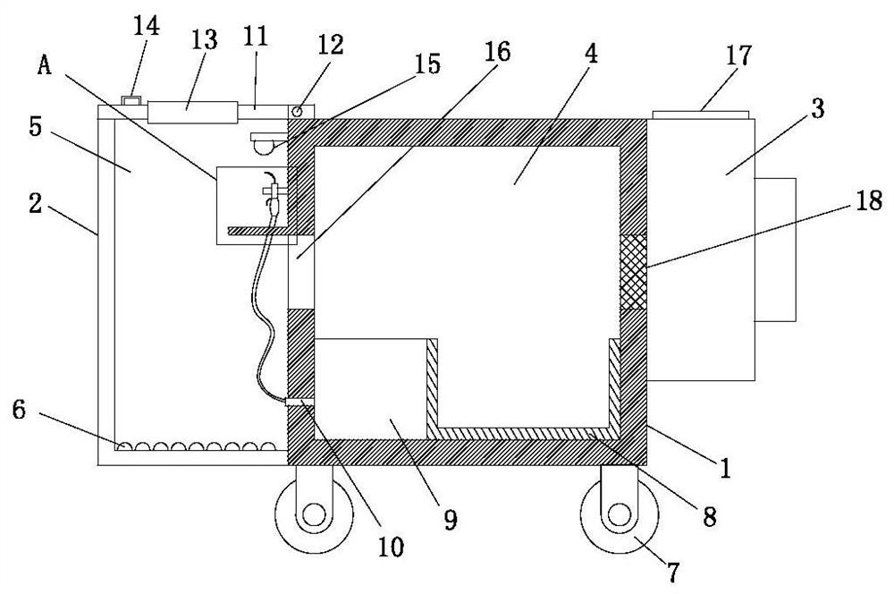
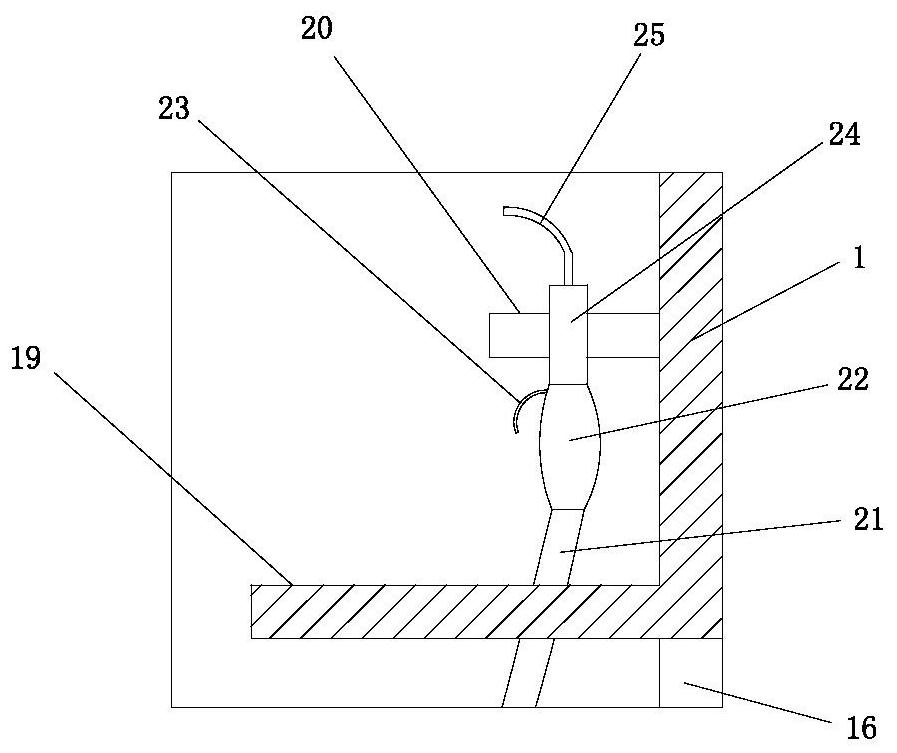
[0036] Such as Figure 1-2 As shown, the present invention provides a PC mainframe dust removal box with good dust removal effect, comprising a dust removal box 2, an ash fall bin 1 and a compression fan 3, the ash fall bin 1 is located between the dust removal box 2 and the compression fan 3, and the ash fall bin 1 is respectively communicated with the dust removal box 2 and the compressor fan 3, the compressor fan 3 is provided with an air outlet 17, the ash bin 1 is provided with a dust collection drawer 8 for collecting dust, and the ash bin 1 is also equipped with a blower 9, the blower 9 A first transmission pipe 10 is provided on the side close to the dust removal box 2, and an air supply hose 21 is installed on the first transmission pipe 10 in the dust removal chamber 5, and an air gun is installed on the side of the air supply hose 21 away from the transmission pipe 10 Handle 22, the side of air gun handle 22 away from air supply hose 21 is equipped with air gun hang...

Embodiment 2

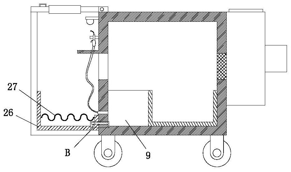
[0042] Such as Figure 3-4 The difference between the second embodiment and the first embodiment is that an equipment bearing frame 26 is installed on the inner bottom of the dust removal box 2, and a bearing platform 27 is installed in the equipment bearing frame 26, and the bearing platform 27 is a grid plate with a wave-shaped structure , the bearing platform 27 and the equipment bearing frame 26 form a cavity, and the side of the blower 9 close to the equipment bearing frame 26 is installed with a first air outlet pipe 28, the first air outlet pipe 28 runs through the ash bin 1 and the equipment bearing frame 26 and extends to the bearing In the cavity formed by the platform 27 and the equipment carrying frame 26 , a first air outlet valve 29 is provided on the first air outlet pipe 28 . By installing the equipment carrying frame 26 at the bottom of the dust removal box 2, the chassis to be dedusted is placed on a corrugated grid plate, and the chassis forms a gap with the...

Embodiment 3

[0044] Such as Figure 5-7 The difference between the third embodiment and the first embodiment is that an equipment carrying drawer 31 is placed on the inner bottom of the dust removal box 2, and a piston 32 is installed at the lower end of the equipment carrying drawer 31, and the piston 32 is installed on the side away from the equipment carrying drawer 26. Piston shaft 33 is arranged, and the side of piston shaft 33 away from equipment bearing drawer 26 is equipped with limiting plate 35, and the side of limiting plate 35 away from piston shaft 33 is equipped with roller mount 36, and roller 37 is installed on the roller mount 36. Place the chassis to be dedusted on the upper end of the equipment load drawer 31, and pull out and send the equipment load drawer 31 by the roller 37, which facilitates the placement and removal of the chassis, and in the process of dust removal, the piston 32 and the piston shaft 33 The cooperation of the roller 37 realizes the shock absorption...


PUM


Abstract

The present invention provides a PC host dust removing box with a sufficient dust removing effect. The PC host dust removing box includes a dust removing box, a dust bin and a compressing blower. Thedust bin is disposed between the dust removing box and the compressing blower and is communicated with the dust removing box and the compressing blower, respectively. The compressing blower is provided with an air outlet. A dust collecting drawer for collecting dust is disposed in the dust bin. A blast blower is further mounted in the dust bin and is provided with a first transmission tube. The first transmission tube is provided with an air hose in a dust removing chamber. The air hose is provided with a pneumatic gun handle. The pneumatic gun handle is equipped with a pneumatic gun hook rail. The pneumatic gun hook rail is equipped with a pneumatic gun sprayer. A pneumatic gun hook rail fixed seat for hanging the pneumatic gun hook rail is mounted on the inner wall of the dust removing box. The dust removing chamber and a dust collecting chamber are communicated via a transmission channel. The dust collecting chamber and the compressing blower are communicated via a filter screen. The PC host dust removing box can efficiently improve dust removing efficiency and quality of the PC host and realize avoiding flying dust during dust removing process.

Description

technical field [0001] The invention relates to the technical field of dust removal equipment, in particular to a PC host dust removal box with good dust removal effect. Background technique [0002] With the implementation of the paperless office of the State Grid Corporation, the utilization rate of PCs is getting higher and higher. According to the requirements of the company's computer configuration, the number of PCs currently operated and maintained by the Xintong Transportation Inspection Center is more than 1,000. Affected by the local environment, after a certain period of time, various components in the host PC will accumulate a lot of dust, especially the PC power supply fan and CPU fan. If the dust cannot be cleaned up in time, it will cause performance degradation of the PC, damage to the power supply, damage to the hard disk, etc., resulting in the inability to guarantee the normal work of employees. Therefore, cleaning the dust of the PC mainframe is one of t...

Claims


Application Information

Patent Timeline
Patent Type & Authority Patents(China)
IPC IPC(8): B08B5/02B08B5/04
CPCB08B5/02B08B5/04
Inventor 方小方王申华曹保良吴辉寿博仁王挺傅建辉孙志文许锦丰蓝忠
Owner 国网浙江武义县供电有限公司
Why Eureka
Try Eureka