Automatic tightening machine

A tightening machine and automatic technology, applied in metal processing, metal processing equipment, manufacturing tools, etc., can solve the problems of unsatisfactory assembly automation and safety, low work efficiency, high labor intensity, etc., and achieve compact structure, solve problems The effect of high labor intensity and reasonable layout

Active Publication Date: 2019-01-08
SHENYANG INST OF AUTOMATION - CHINESE ACAD OF SCI
View PDF6 Cites 18 Cited by
  • Summary
  • Abstract
  • Description
  • Claims
  • Application Information

AI Technical Summary

Problems solved by technology

Not only the labor intensity is high, but the work efficiency is low, and it is dangerous
In the field of production and assembly of shells and small-caliber missiles in China, there is no equipment that can realize automatic tightening. The current operation method cannot meet the requirements of automation and safety of projectile assembly.

Method used


Image

  • Automatic tightening machine
  • Automatic tightening machine
  • Automatic tightening machine

Examples


Embodiment 1

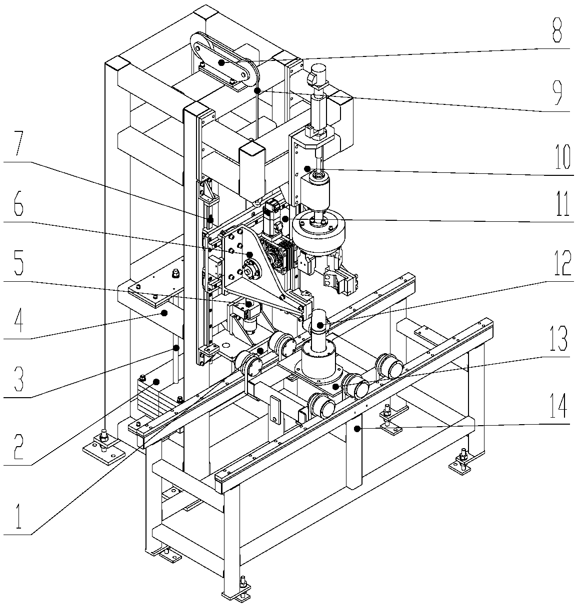
[0028] Such as Figure 1-2 As shown, an automatic tightening machine provided by the present invention includes a frame 4, a tightening unit 10 and a clamping unit 6, wherein the tightening unit 10 is arranged on the frame 4, and the clamping unit 6 is arranged below the tightening unit 10, And connected with the frame 4, the tightening unit 10 and the clamping unit 6 can move relatively, and realize the tightening of the workpiece through mutual cooperation.

[0029] The automatic tightening machine also includes a lifting slide 11 and a lifting drive mechanism. The frame 4 is vertically provided with a lifting slide guide rail 7. The lifting slide 11 is slidingly connected with the lifting slide guide 7. The lifting drive mechanism is arranged on the frame 4 and is connected with the lift slide 11. The clamping unit 6 is arranged on the lifting slide 11 , and the tightening unit 10 is fixed on the upper end of the frame 4 .

[0030] The lifting drive mechanism includes a l...

Embodiment 2

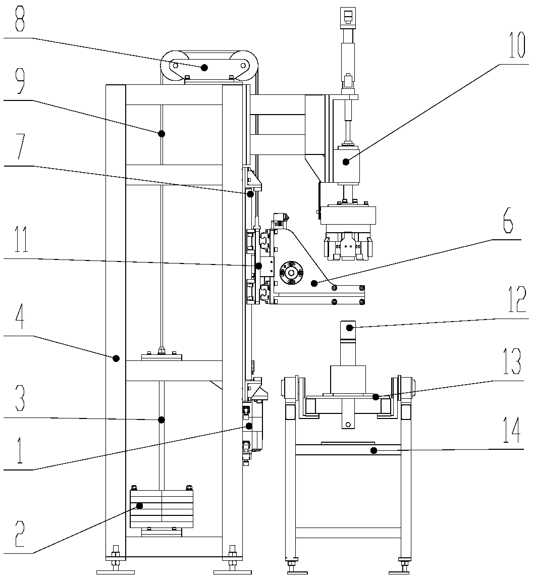
[0046] Such as Figure 5-6 As shown, a kind of automatic tightening machine provided by the present invention comprises frame 4, tightening unit 10, clamping unit 6, lifting slide table 11 and lifting driving mechanism, wherein frame 4 is provided with lifting slide table along vertical direction The guide rail 7 and the lift slide table 11 are slidingly connected with the lift slide table guide rail 7, and the lift drive mechanism is arranged on the frame 4 and connected with the lift slide table 11. The tightening unit 10 is arranged on the lifting slide 11, and the lifting slide 11 can drive the tightening unit 10 to move up and down. The clamping unit 6 is arranged below the tightening unit 10, and the clamping unit 6 is installed on the transmission line body 14 located on one side of the frame 4. The tightening unit 10 and the clamping unit 6 can move relatively, and realize the fixing of the workpiece by mutual cooperation. Tighten.

[0047] The clamping unit 6 includ...


PUM


Abstract

The invention relates to a tightening machine, in particular to the tightening of large threads between different sections of a projectile and a small-caliber missile. The tightening machine includesa rack, a tightening unit, a clamping unit, a lifting slide table and a lifting drive mechanism, wherein the lifting slide table is slidably connected to the rack, the lifting drive mechanism is arranged on the rack and connected with the lifting slide table, and the clamping unit or the tightening unit is arranged on the lifting slide table; when the clamping unit is disposed on the lifting slidetable, the tightening unit is fixed to the upper end of the rack; when the tightening unit is disposed on the lifting slide table, the clamping unit is disposed on a transmission line body, and the tightening unit and the clamping unit achieve the tightening of a workpiece by mutual cooperation. The automatic tightening machine can realize automatic tightening and solve the problems of high laborintensity, low work efficiency and certain risk in the existing tightening process. The automatic tightening machine has the advantages of compact structure, reasonable layout and wide adaptability,and can be used for direct operation in a product pallet station of a production line.

Description

technical field [0001] The invention belongs to the technical field of body assembly, and in particular relates to an automatic screwing machine. Background technique [0002] During the assembly process of artillery shells and small-caliber missiles, different compartments such as the seeker, warhead, control cabin, and engine need to be tightened and combined, and there are tightening torque requirements. The existing tightening process is generally to move the product away from the transmission line body, manually install the tightening tooling, pre-tighten, and then perform automatic or manual tightening. The tightening process is semi-automatic or fully manual, requiring manual participation. Not only labor intensity is big, work efficiency is low, and has certain danger. There is no automatic tightening equipment in the field of production and assembly of shells and small-caliber missiles in China, and the current operation method cannot meet the requirements of auto...

Claims


Application Information

Patent Timeline
Patent Type & Authority Applications(China)
IPC IPC(8): B23P19/04
CPCB23P19/04
Inventor 郭爱波张延利徐永利白鑫林刘勇李峰王军义刘明洋徐宁
Owner SHENYANG INST OF AUTOMATION - CHINESE ACAD OF SCI
Why Eureka
Try Eureka