Hydraulic clamping device for hardware numerical control machining

A hydraulic clamping and hardware technology, which is applied in the direction of clamping devices, metal processing equipment, metal processing machinery parts, etc., can solve problems such as unstable clamping of hardware parts, influence on sales of hardware parts, easy damage to hardware parts, etc., to avoid The outer surface is damaged, the clamping effect is good, and the effect of clamping stability

Active Publication Date: 2019-01-08
江苏天佑液压科技有限公司
View PDF7 Cites 4 Cited by
  • Summary
  • Abstract
  • Description
  • Claims
  • Application Information

AI Technical Summary

Problems solved by technology

[0003] When processing hardware products, CNC lathes are usually used to process them. However, when the existing CNC lathes clamp the hardware, they usually can only clamp the hardware from two faces. The clamping method of the hard

Method used


Image

  • Hydraulic clamping device for hardware numerical control machining
  • Hydraulic clamping device for hardware numerical control machining
  • Hydraulic clamping device for hardware numerical control machining

Examples


Example Embodiment

[0021] The technical solutions in the embodiments of the present invention will be clearly and completely described below with reference to the accompanying drawings in the embodiments of the present invention. Obviously, the described embodiments are only a part of the embodiments of the present invention, but not all of the embodiments.

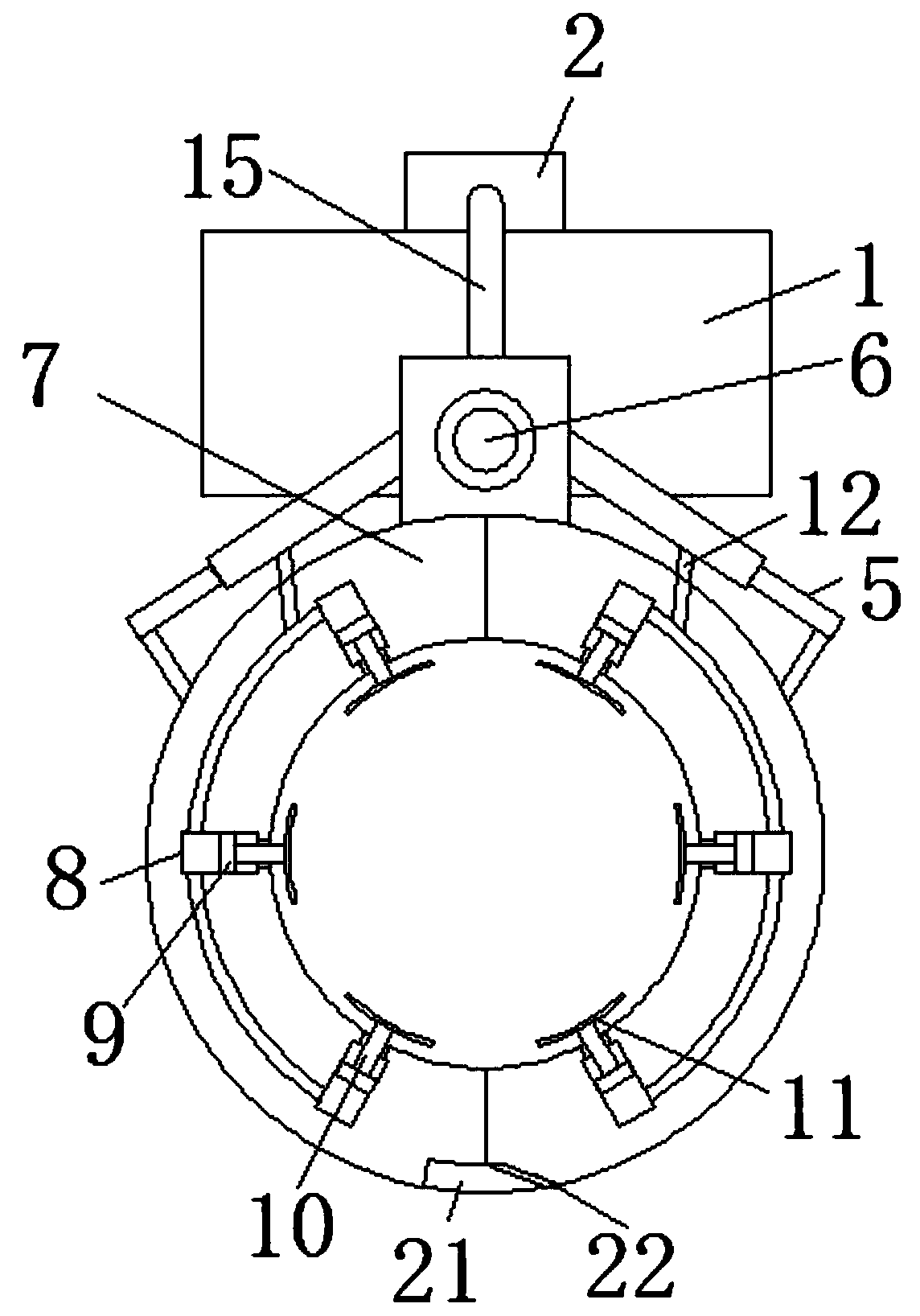
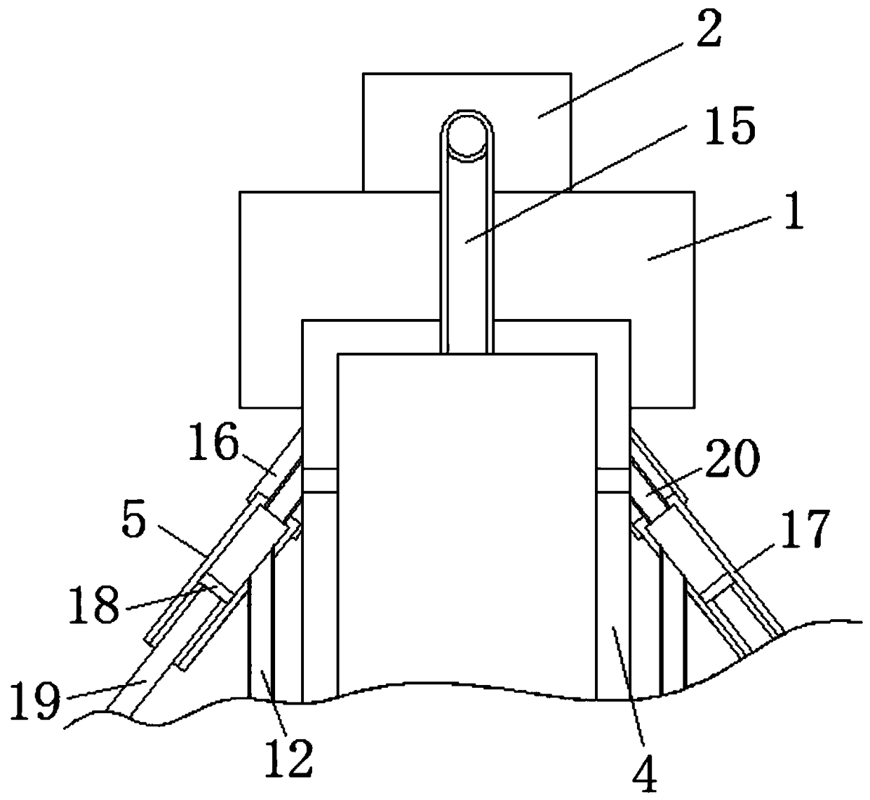
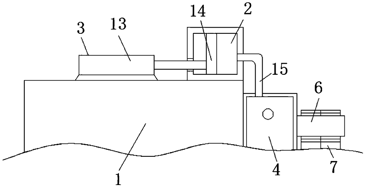
[0022] refer to Figure 1-3 , a hydraulic clamping device for hardware CNC machining, comprising a mounting part 1, a liquid storage tank 2 is fixedly connected to the top of the mounting part 1, and a pushing mechanism whose front end extends to the interior of the liquid storage tank 2 is fixedly connected to the top of the mounting part 1 3. The front of the mounting member 1 is fixedly connected to the liquid separator 4 which is connected to the liquid storage tank 2. The pushing mechanism 3 includes an electric push rod 13 that is fixedly connected to the top of the mounting member 1. The front end of the electric push rod 13 is connec...


PUM


Abstract

The invention discloses a hydraulic clamping device for hardware numerical control machining. The hydraulic clamping device comprises a mounting member. The top of the mounting member is fixedly connected with a liquid storage tank. The top of the mounting member is fixedly connected with a pushing mechanism of which the front end extends into the liquid storage tank. The front face of the mounting member is fixedly connected with a liquid distribution tank communicating with the liquid storage tank. Pushing rods communicating with the liquid distribution tank are hinged to the left side walland the right side wall of the liquid distribution tank. The front face of the liquid distribution tank is fixedly connected with a rotating shaft. The structure of the hydraulic clamping device is reasonable, hydraulic oil in the pushing rods enters an accommodating groove through a hose and can push a moving plate to move by pouring into the accommodating groove, thus, a squeezing rod and a curved plate are enabled to move through movement of the moving plate, and hardware can be further clamped through movement of the squeezing rod and the curved plate, so that the hardware is clamped morestably, the hardware can be clamped in different directions, and the situation that stress points of the hardware are few, and consequently the outer surface of the hardware is damaged is avoided.

Description

technical field [0001] The invention relates to the technical field of hardware processing, in particular to a hydraulic clamping device for hardware numerical control processing. Background technique [0002] Hardware: traditional hardware products, also known as "hardware". Refers to the five metals of gold, silver, copper, iron, and tin. After manual processing, it can be made into works of art or metal devices such as knives and swords. Hardware in modern society is more extensive, such as hardware tools, hardware parts, daily hardware, construction hardware and security supplies. The hardware industry is developing very fast. The most concentrated domestic markets in the traditional hardware industry are mainly concentrated in mechanical hardware, architectural hardware, decorative hardware, and daily hardware. [0003] When processing hardware products, CNC lathes are usually used to process them. However, when the existing CNC lathes clamp the hardware, they usuall...

Claims


Application Information

Patent Timeline
IPC IPC(8): B23Q3/00
CPCB23Q3/00B23Q2703/04
Inventor 罗刚
Owner 江苏天佑液压科技有限公司
Why Eureka
Try Eureka