impact device

A technology of impact device and guide part, which is applied in the direction of impact tools, light impact tools, manufacturing tools, etc., can solve the problems of uneven impact force, damage, crank pin damage, etc., to ensure uniform movement direction, force transmission, Ease of exit

Active Publication Date: 2021-02-26
东营仁合石油机械设备有限公司
View PDF17 Cites 0 Cited by
  • Summary
  • Abstract
  • Description
  • Claims
  • Application Information

AI Technical Summary

Problems solved by technology

When dismantling and replacing the crank pin, the user usually needs to hold a sledgehammer to strike it from one side of the crank pin, and the striking position of the crank pin by the sledgehammer is controlled by the user, which is difficult to control. It often causes phenomena such as smashing, and there is also the problem of uneven impact force caused by manual knocking, which is easy to cause damage to the crank pin, and in severe cases, it will damage other components used in conjunction with the crank pin
Moreover, this operation method requires high professional ability of the user, consumes a long construction period, and is easy to cause problems such as scrapping parts

Method used


Image

  • impact device
  • impact device

Examples


Embodiment 1

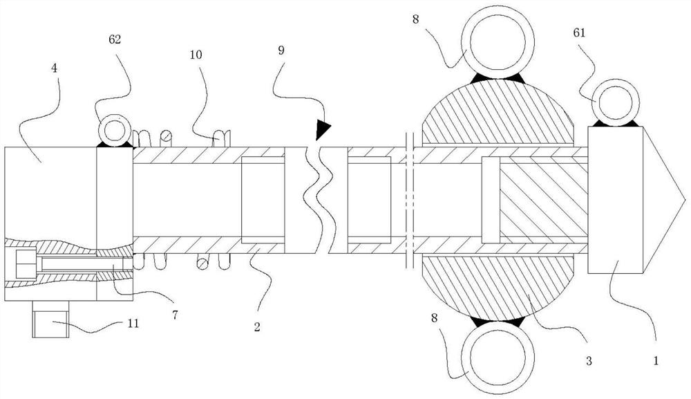
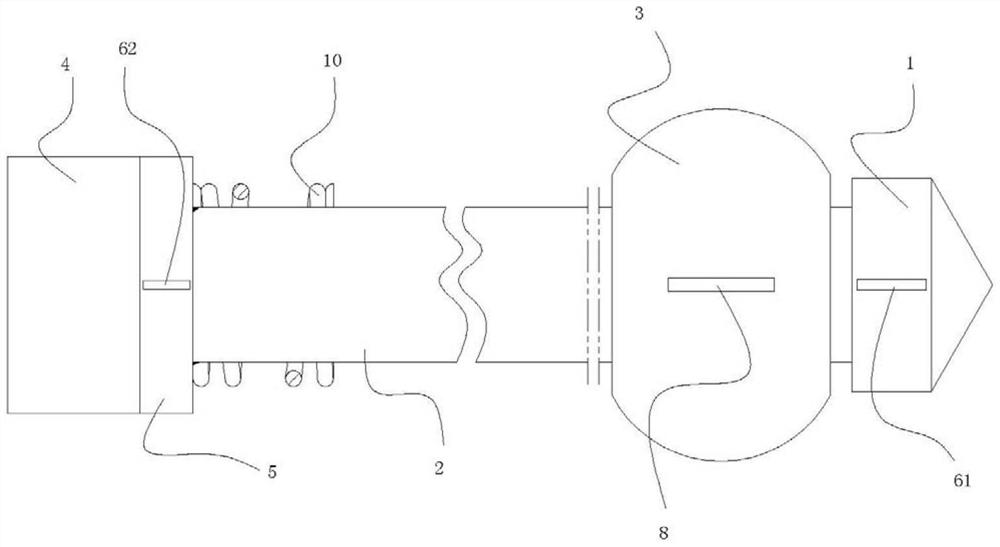
[0061] like figure 1 , figure 2 As shown, the impact device in this embodiment includes a center-of-gravity adjustment part that connects the guide part and the pressure supply part. When facing downwards, the center of gravity of the device is set along the direction of gravity. With the impact device introduced in this embodiment, the setting of the center of gravity adjustment part can further ensure the stability of the center of gravity of the device. During the sliding process of the sliding part, it is inevitable that there will be hidden dangers of changes in the direction of force applied by the user or changes in the position of the center of gravity of the device. The design of the center of gravity adjustment part is added to the device introduced in the present invention, so that the center of gravity of the device is obviously biased towards the lower side of the device, which is consistent with the direction of gravity. Similarly, even if the center of gravit...

Embodiment 2

[0065] like figure 1 , figure 2 As shown, the difference between the impact device in this embodiment and the above embodiments is that: the impact device includes a first positioning portion for positioning the tip, and the first positioning portion is arranged on one side of the tip. Preferably, the first positioning part is arranged on the other side of the center of gravity of the center of gravity adjustment part relative to the tip part. Then the projection of the connection line between the first positioning part and the center-of-gravity adjusting part in the vertical direction is the vertical direction, which is the same as the direction of gravity. The first positioning part suspends the device above the device, and the center-of-gravity adjusting part adjusts the direction of suspension below, thereby realizing the positioning and position adjustment of the device.

[0066] Further preferably, the first positioning part in this embodiment is a ring structure, whi...

Embodiment 3

[0071] like figure 1 , figure 2 As shown, the difference between the impact device in this embodiment and the above embodiment is that the impact device includes an operating part for controlling the sliding of the sliding part, the operating part is connected to the sliding part, and the number of operating parts is at least two, at least two The operating parts are arranged oppositely; the operating part is a ring structure.

[0072] Through the impact device introduced in this embodiment, the design of the operation part can assist the user to control the sliding part more conveniently. The number and setting positions of the operating parts can be designed and adjusted according to the needs of users. Preferably, the angle range between the operating parts is within the range of 60-180°. A rope can be connected to the operating part, which is convenient for the user to grasp the sliding part.

[0073] Further, the impact device in this embodiment includes a hydraulic t...


PUM


Abstract

The invention discloses an impact device, comprising a guide part, a tip part arranged at one end of the guide part, a pressure providing part arranged on the guide part, capable of rotating around the guide part and moving along with the guide part. A sliding part that is axially slidably connected, and the sliding part is located between the tip part and the pressure supply part. The impact device disclosed in the present invention can achieve easier disassembly of the crank pin without special training for the user, and the impact force of the impact device on the crank pin is evenly distributed and the impact position is accurate. Avoid damage to the crank pin and significantly improve removal efficiency.

Description

technical field [0001] The invention belongs to the field of production tools, and in particular relates to an impact device. Background technique [0002] In the prior art, the beam pumping unit in the petroleum enterprise uses an important kinematic pair——the crank pin to make the oil beam move up and down during operation, so as to lift the underground oil to the ground. The crank pin of the pumping unit is an important part of the pumping unit. When the pumping unit is running, the crank transmits torque to the connecting rod through the crank pin assembly. The crank pin assembly is a key stress-bearing part with a large load in the whole pumping unit parts. If the crank pin breaks, the whole pumping unit may be scrapped, causing significant economic losses. The main factors causing damage to the crank pin include excessive load of the pumping unit; unbalanced pumping unit; wear and tear of the pin in the pin hole, causing shaking; scissors difference beyond the range; ...

Claims


Application Information

Patent Timeline
Patent Type & Authority Patents(China)
IPC IPC(8): B25D9/00B25D17/02B25D17/08
CPCB25D9/00B25D17/02B25D17/08
Inventor 贾连山王炬陈军
Owner 东营仁合石油机械设备有限公司
Why Eureka
Try Eureka