
A liftable service robot

A service robot and lifting technology, which is applied in the field of robots, can solve the problem that service robots do not have adjustable height functions, and achieve the effects of improving human-computer interaction, safe comprehensive operations, and ensuring economic benefits

Active Publication Date: 2021-12-17
昆山谷航信息科技有限公司
View PDF14 Cites 0 Cited by
  • Summary
  • Abstract
  • Description
  • Claims
  • Application Information

AI Technical Summary

Problems solved by technology

[0004] The purpose of the present invention is to provide a liftable service robot, which has the advantage of adjustable height and solves the problem that common service robots do not have the function of adjustable height

Method used


Image

  • A liftable service robot
  • A liftable service robot
  • A liftable service robot

Examples


no. 1 approach

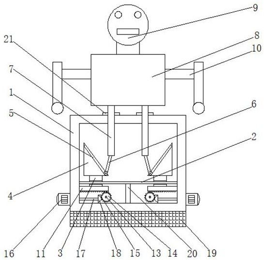
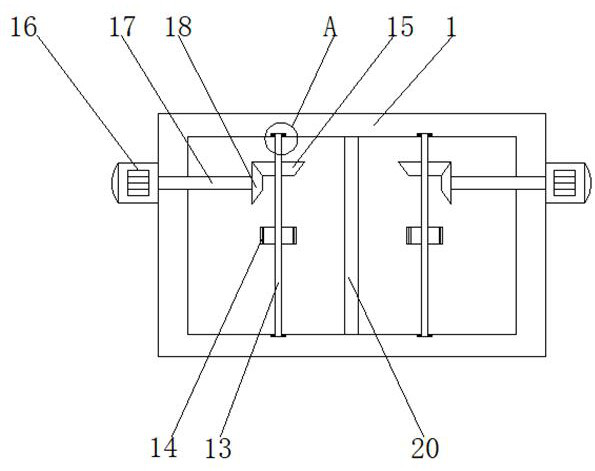
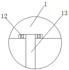
[0018] First implementation: see Figure 1-3 , as shown in claim 1, a liftable service robot includes a housing 1, the left and right sides of the inner wall of the housing 1 are fixedly connected by slide bars 2, and the bottom of the housing 1 is fixedly connected with an anti-slip block 19, which prevents slipping The surface of the block 19 is provided with anti-slip lines. By setting the anti-slip block 19, the service robot is prevented from sliding due to external force. The left and right sides of the surface of the slide bar 2 are movably connected with a slider 3, and the top of the slider 3 is fixedly connected with a triangle. Block 4, the top of the triangular block 4 is provided with a chute 5, the inside of the chute 5 is movably connected with a pulley 6, the top of the pulley 6 runs through the chute 5 and extends to its outside to be fixedly connected with a support column 7, and the support column 7 is left and right. The position on the side and at the top ...

no. 2 approach

[0021] The second embodiment: a liftable service robot, including a housing 1, the left and right sides of the inner wall of the housing 1 are fixedly connected by a slide bar 2, and the left and right sides of the surface of the slide bar 2 are movably connected with slide bars. Block 3, the top of each slide block 3 is fixedly connected with a triangular block 4, the top of the triangular block 4 is provided with a chute 5, the inside of the chute 5 is movably connected with a pulley 6, and the pulley 6 The top of the support column 7 penetrates through the chute 5 and extends to the outside, and then is fixedly connected to the support column 7 through an inclined connecting rod. The top of the support column 7 extends to the outside through two through holes on the housing 1. The top of each support column 7 is connected with the robot main body 8 in rotation, and the midpoint of the top of the robot main body 8 is fixedly connected with the robot head 9, and the left and r...


PUM


Abstract

The invention discloses a liftable service robot, which comprises a shell, the left and right sides of the inner wall of the shell are fixedly connected by a slide bar, the left and right sides of the surface of the slide bar are movably connected with sliders, the slide The top of the block is fixedly connected with a triangular block, the top of the triangular block is provided with a chute, the inside of the chute is movably connected with a pulley, and the top of the pulley runs through the chute and extends to the outside to be fixedly connected with a support column. The present invention cooperates with each other through the sliding rod, sliding block, triangular block, chute, pulley, support column, rack, rolling bearing, driven shaft, gear, driven bevel gear, positive and negative motor, positive and negative shaft and driving bevel gear, It has the function of enabling the service robot to have an adjustable height, which can be used by people of different heights, improves the effect of human-computer interaction, improves the practicability of the service robot, is conducive to the promotion of merchants, and ensures the economic benefits of manufacturers.

Description

technical field [0001] The invention relates to the technical field of robots, in particular to a liftable service robot. Background technique [0002] In contemporary industry, a robot refers to a man-made machine device that can automatically perform tasks to replace or assist human work. The ideal high-simulation robot is an advanced integration of cybernetics, mechatronics, computer and artificial intelligence, materials science and bionics. Product, at present, the service robot industry has developed rapidly, and the application range of service robots is very wide. [0003] However, common service robots do not have the function of adjustable height, and cannot adjust the corresponding height according to the different heights of different groups of people. Promotion in the market has seriously affected the economic benefits of manufacturers. Contents of the invention [0004] The object of the present invention is to provide a liftable service robot, which has th...

Claims


Application Information

Patent Timeline
Patent Type & Authority Patents(China)
IPC IPC(8): B25J11/00B25J19/00
CPCB25J9/0009B25J11/008
Inventor 郭玉华
Owner 昆山谷航信息科技有限公司
Learn More