
Vertical type tire dismounting device

A tire disassembly and vertical technology, which is applied in tire installation, tire parts, transportation and packaging, etc., can solve the problems of inability to adjust the working position of the pry board, the slipping of the rear end of the connecting rod, and the inability to adjust the working position, etc. , to achieve the effect of saving working time, reasonable and stable structure, and novel design

Inactive Publication Date: 2019-01-08
大力汽保(营口)装备制造有限公司
View PDF11 Cites 3 Cited by
  • Summary
  • Abstract
  • Description
  • Claims
  • Application Information

AI Technical Summary

Problems solved by technology

[0019] Although the structure of the above-mentioned device seems simple, it has a very large hidden danger in use. When the horizontal limit shaft is used to withstand the rear end of the connecting rod, the problem that the rear end of the connecting rod will slip and cannot be supported after a period of use is prone to occur.
At the same time, the skid plate cannot adjust the working position of the skid plate, which cannot be achieved for some tires that require the deep position of the skid plate to be inserted.
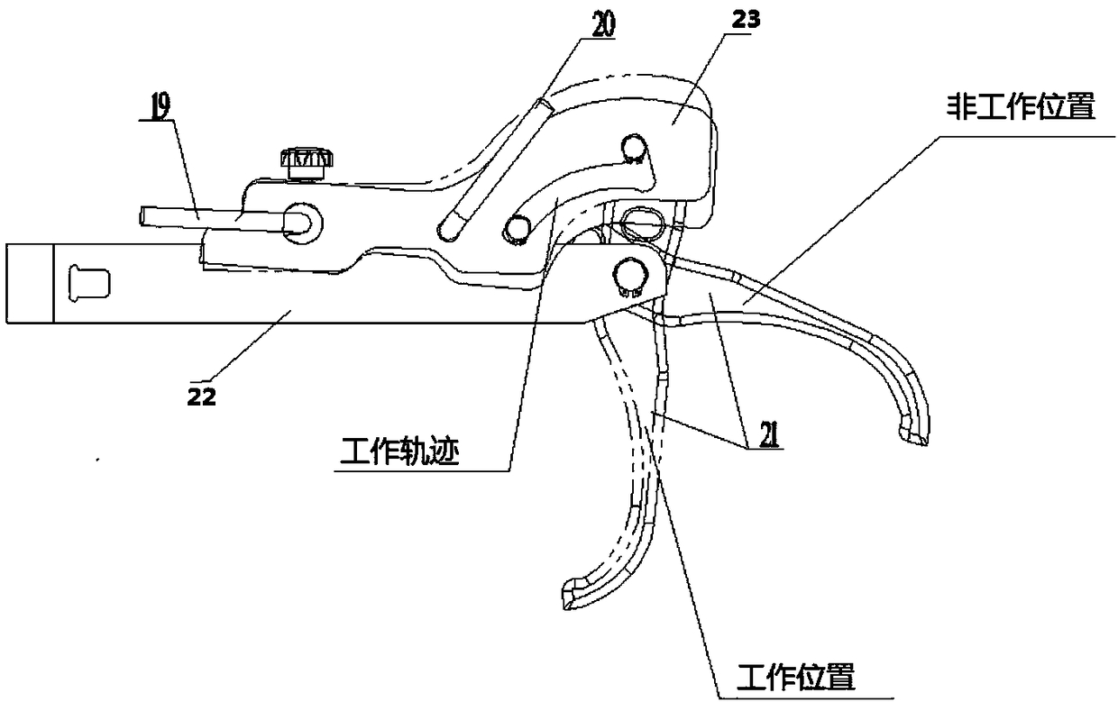
[0020] Another object of the present invention is to propose a new crowbar (tire removal hook) assembly, which not only solves the technical problem that the above crowbar cannot adjust the working position, but also improves the safety of use

Method used


Image

  • Vertical type tire dismounting device
  • Vertical type tire dismounting device
  • Vertical type tire dismounting device

Examples


Embodiment Construction

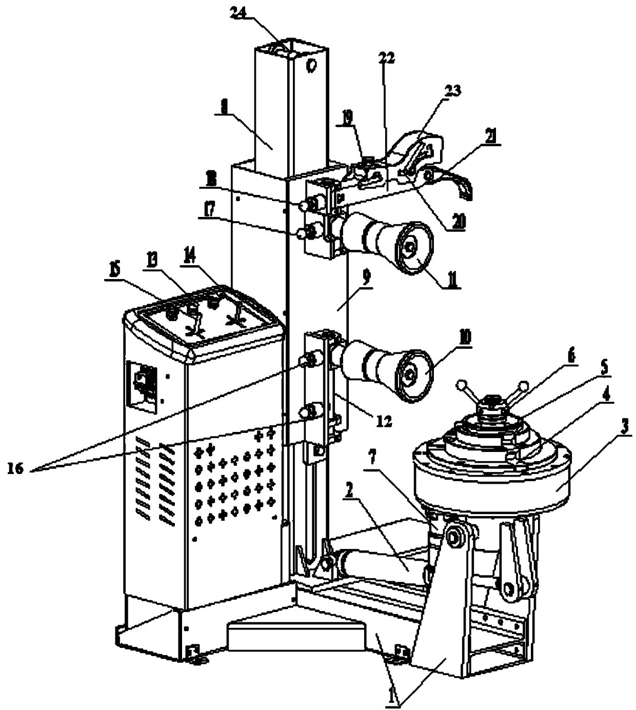
[0042] Such as Figure 1-Figure 5 As shown, the main structure of the vertical tire changing device of the present invention includes three parts: a base 1 , a column 8 and a console 13 .

[0043] When using this device to remove tires, it is necessary to stabilize the base 1, the column 8 and the console 13 at the same plane position, and the console 13 is the electrical and hydraulic power control assembly of the whole device.

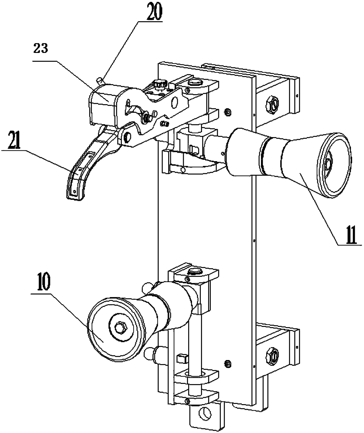
[0044] The tire removal hook assembly, the lower dismounting tire pressure roller 10 and the upper dismounting tire pressure roller 11 are in the non-working position when not in use, and the non-working position is perpendicular to the plane formed by the column and the round platform, that is, the parts are opposite to each other. Swing 90° horizontally to the left in the longitudinal direction of the column. When the tire removal hook assembly, the lower dismounting tire pressure roller 10 and the upper dismounting tire pressure roller 11 are in ...


PUM


Abstract

The invention relates to a vertical type tire dismounting device. The device comprises a stand column and a base; a pullet assembling assembly is arranged on the stand column; two dismounting tire pressure rolls which are capable of swinging horizontally are arranged on the pulley assembling assembly; a tire dismounting hook assembly is arranged on the pulley assembling assembly; the tire dismounting hook assembly comprises a tire dismounting hook bracket, a hook locking box, a tire dismounting hook locking device, a tire dismounting hook unlocking device and a tire dismounting hook; the hooklocking box is internally provided with a slide rail; a reversible round table is arranged on the base; and a rotating clamping disk and a plurality of slide rails which are distributed in the radialdirection are arranged on the round table. The device is capable of overcoming the disadvantage of large-scale vertical type tire dismounting machines in the prior art and effectively shortening the height of the stand column, is novel in design, reasonable and stable in structure, easy to operate, convenient, practical and durable, and is capable of dismounting tires more efficiently, improving the working efficiently and saving the working time.

Description

[0001] The application of the present invention is a divisional application with the application number 201710279300.1, the application date is April 25, 2017, and the invention name is "a vertical tire dismounting device". technical field [0002] The invention relates to the technical field of dismounting and assembling of large and medium-sized tires, in particular to a vertical dismounting device for large and medium-sized tires. Background technique [0003] Most of the large and medium-sized tires of buses, light trucks, and construction vehicles running on the road are tubeless tires (that is, vacuum tires) composed of two parts, the outer tire and the rim, and some tires are tires with inner tubes or with open pressure rings. tire. [0004] The traditional method of manually disassembling tires has long been unable to meet the needs of existing tire disassembly. It is an irresistible trend to use mechanical equipment to replace traditional manual tire disassembly. A...

Claims


Application Information

Patent Timeline
Patent Type & Authority Applications(China)
IPC IPC(8): B60C25/05B60C25/138
CPCB60C25/053B60C25/0563B60C25/138B60C25/0539B60C25/0578
Inventor 宗海
Owner 大力汽保(营口)装备制造有限公司
Learn More