Pan/tilt and an unmanned aerial vehicle with same

A pan-tilt and body technology, applied in the field of aircraft, can solve the problem of high height of the UAV, and achieve the effect of reducing the height, reducing the vertical height and increasing the distance

Pending Publication Date: 2019-01-08
GOERTEK ROBTICS CO LTD
View PDF0 Cites 1 Cited by
  • Summary
  • Abstract
  • Description
  • Claims
  • Application Information

AI Technical Summary

Problems solved by technology

[0004] In view of this, the first object of the present invention is to provide a kind of cloud platform, the structural design of this platform can effectively sol

Method used


Image

  • Pan/tilt and an unmanned aerial vehicle with same
  • Pan/tilt and an unmanned aerial vehicle with same
  • Pan/tilt and an unmanned aerial vehicle with same

Examples


Example Embodiment

[0031] The embodiment of the invention discloses a pan / tilt, which can reduce the height of the whole drone.

[0032] The technical solutions in the embodiments of the present invention will be clearly and completely described below in conjunction with the accompanying drawings in the embodiments of the present invention. Obviously, the described embodiments are only a part of the embodiments of the present invention, rather than all the embodiments. Based on the embodiments of the present invention, all other embodiments obtained by those of ordinary skill in the art without creative work shall fall within the protection scope of the present invention.
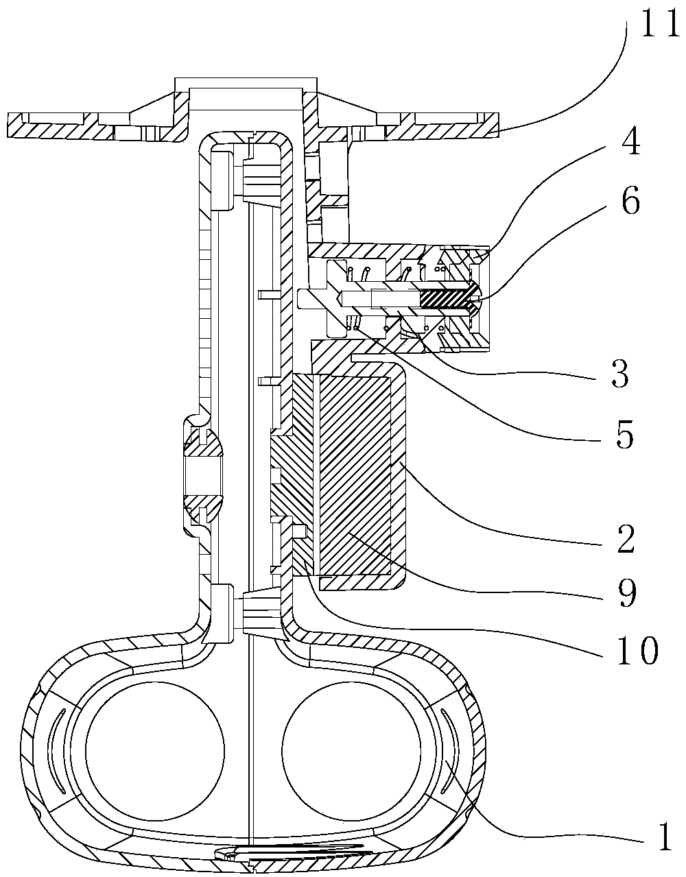
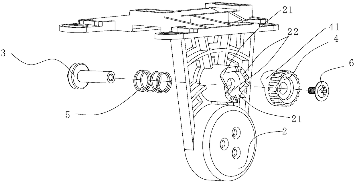
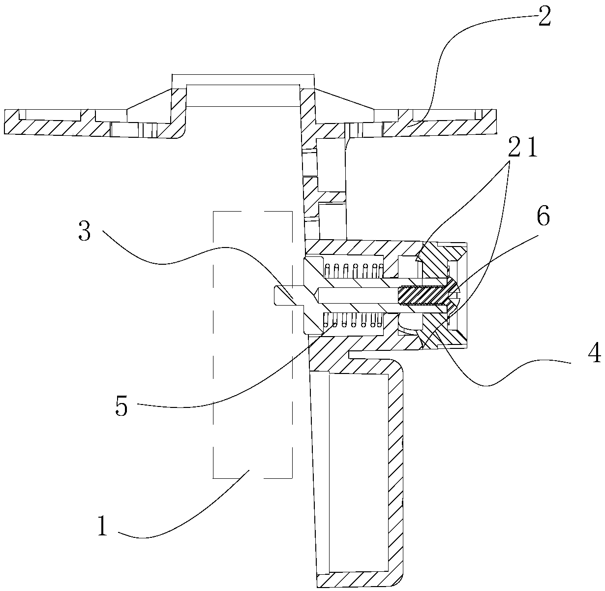
[0033] See Figure 1-Figure 2 , figure 1 Is a schematic diagram of a cross-sectional structure of a pan-tilt according to a specific embodiment of the present invention; figure 2 Schematic diagram of the explosive structure of the locking mechanism.

[0034] In a specific embodiment, the pan / tilt provided by the present invention i...


PUM


Abstract

The invention discloses a pan/tilt and an unmanned aerial vehicle with same. The pan/tilt comprises a pan/tilt body, a motor and a bracket, wherein the bracket is used for supporting the platform body, one of a stator and a rotor of the motor is fixedly connected with a bracket, The other is fixedly connected with the shell of the platform body, and the rotor is rotated relative to the stator whenthe motor is working, so as to drive the platform body relative to the bracket to move in the range from the vertical state to the rotation preset angle, and the platform body can be stored in the protective cover of the unmanned aerial vehicle when the platform body relative to the bracket is rotated to the preset angle. The head and the unmanned aerial vehicle can rotate and fold the head bodyupward through a motor during the landing process of the unmanned aerial vehicle, thereby reducing the vertical height and increasing the distance between the head and the ground. And can be folded into the shield of the unmanned aerial vehicle by the preset angle setting, so that the contact between the platform body and the ground can be avoided by the shield when landing, the landing gear is not required, and the height of the whole aircraft is further reduced.

Description

technical field [0001] The present invention relates to the field of aircraft technology, more specifically, to a cloud platform, and also to an unmanned aerial vehicle with the platform. Background technique [0002] The PTZ is a supporting device for installing and fixing the camera. When the UAV carries the camera equipment, it usually connects the pan-tilt by fixing it on the fuselage, and then installs the camera equipment on the pan-tilt. However, the gimbal is usually larger in size and longer in length. In order to avoid the contact between the gimbal and the ground when landing, it is necessary to set up a long landing gear for support, which makes the height of the whole machine larger, which is not conducive to the miniaturization design of the UAV. [0003] To sum up, how to effectively solve the problem that the overall height of the UAV is too high is a problem that those skilled in the art need to solve. Contents of the invention [0004] In view of this,...

Claims


Application Information

Patent Timeline
IPC IPC(8): B64D47/08
CPCB64D47/08B64U2101/30
Inventor 姚俊青仲强
Owner GOERTEK ROBTICS CO LTD
Why Eureka
Try Eureka