
Shearing fork lifting assembly and shearing fork lifting system

A technology of lifting components and lifting systems, applied in the direction of lifting devices, etc., can solve the problems of unfavorable support platform stability, support center offset, and lower stability, and achieve continuous smooth driving process, ensure stability, and ensure isotropy Effect

Active Publication Date: 2019-01-08
航天时代(青岛)海洋装备科技发展有限公司
View PDF5 Cites 2 Cited by
  • Summary
  • Abstract
  • Description
  • Claims
  • Application Information

AI Technical Summary

Problems solved by technology

[0004] Because the support points of the scissor lifting assembly to the support platform are the fixed points of the two ribs and the support platform, and the fixed point of one of the ribs and the support platform slides with the drive of the hydraulic drive assembly , resulting in the offset of the support center of the support platform by the scissor lifting assembly, which is not conducive to the stability of the support platform
At the same time, the shape of the traditional scissor lift mechanism is mostly a square prism, and its performance in different directions is different, which further reduces the stability during work.

Method used


Image

  • Shearing fork lifting assembly and shearing fork lifting system
  • Shearing fork lifting assembly and shearing fork lifting system
  • Shearing fork lifting assembly and shearing fork lifting system

Examples


specific Embodiment

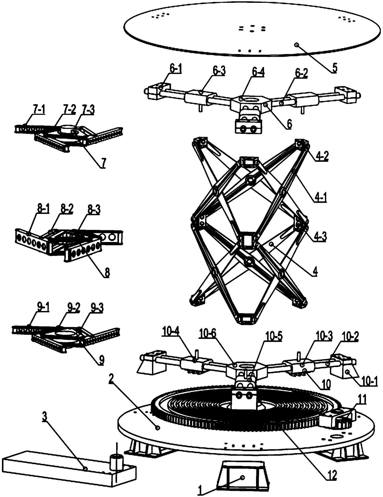
[0047] see figure 1 , the embodiment of the present invention provides a spiral three-dimensional scissors lifting platform, including a base leg 1, a lifting base 2, a drive motor 3, a scissor mechanism 4, an upper platform 5, a second sliding guide assembly 6, and an upper platform synchronization bracket 7. Central synchronous bracket 8, base synchronous bracket 9, first sliding guide assembly 10, driving gear 11, helical gear plate 12.

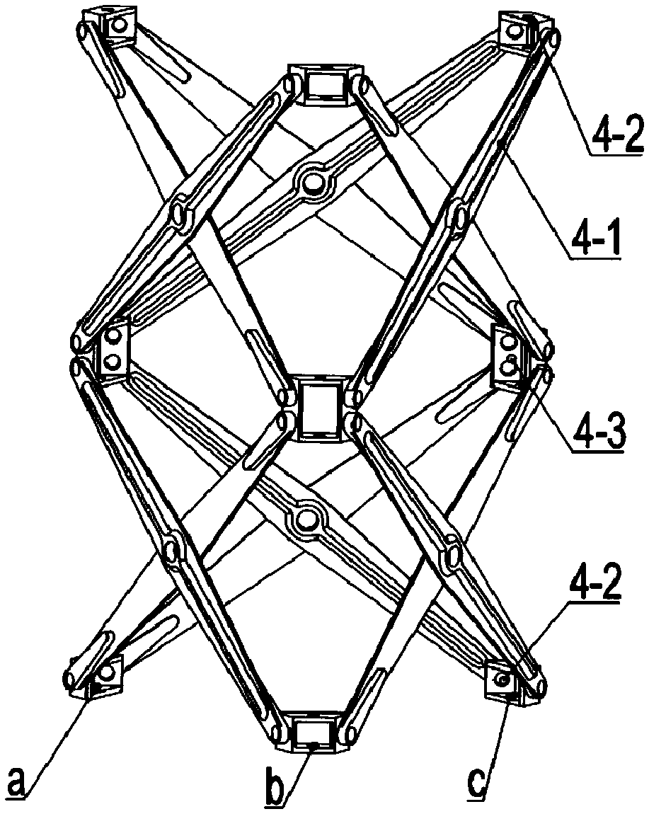
[0048] The scissor mechanism 4 is composed of multi-layer scissor lifting components, each layer of scissor lifting components is composed of 6 pieces of scissor ribs 4-1, and the scissor ribs 4-1 are in groups of two, and the ends of the scissor ribs are respectively used The rotating shaft is connected with the single-layer fin transfer corner fitting 4-2 and the double-layer fin transfer corner fitting 4-3, which can rotate freely around the shaft and form an equilateral triangle. Between each group of scissor fins 4-1 The middle part ...


PUM


Abstract

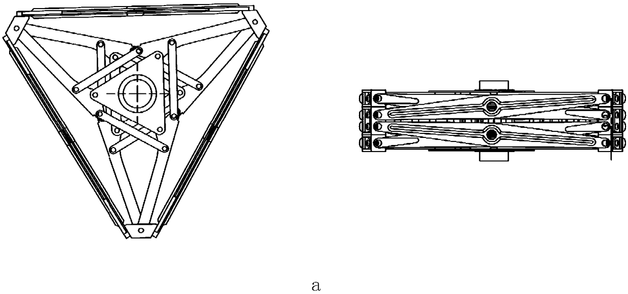
The invention relates to a shearing fork lifting assembly and a shearing fork lifting system, and belongs to the field of lifting platforms. The shearing fork lifting assembly comprises three sets ofshearing fork structures, and each set of shearing fork structure comprises two shearing fork ribs arranged in a crossed manner, wherein the two shearing fork ribs are rotatably connected at the intersection position; and the three sets of shearing fork structures define a circle, the upper ends of the shearing fork ribs of every two adjacent shearing fork structures are rotatably connected to form three first connecting points, the lower ends of the shearing fork ribs of every two adjacent shearing fork structures are rotationally connected to form three second connection points, the three planes where the three sets of shearing fork structures are located form a triangular prism structure, the first connection points are used for being connected with a support platform assembly, and thesecond connection points are used for being connected with a lifting base. The shearing fork lifting assembly and the shearing fork lifting system guarantee stability of the support platform, are suitable for lifting and handling of large heavy-duty cargoes, and are suitable for high-precision controllable lifting of light cargoes.

Description

technical field [0001] The invention relates to a scissor lifting assembly and a scissor lifting system, belonging to the field of lifting platforms. Background technique [0002] Lifting aerial work platforms are widely required for material handling in narrow and airtight environments, maintenance and inspection of large equipment such as wind power stations, aircraft, and ships, and construction operations. [0003] At present, the widely used scissor lift mechanism includes a base, two sets of scissor lift assemblies, a support platform and a hydraulic drive assembly, the two sets of scissor lift assemblies are arranged in parallel on the base, and the support platforms are fixed on The upper ends of the two groups of scissor lift assemblies, the scissor lift assemblies include two intersecting ribs, the two ribs are rotatably connected, and one end of the ribs is fixedly connected to the base or the On the support platform, the other end slides with the drive of the hy...

Claims


Application Information

Patent Timeline
IPC IPC(8): B66F11/00B66F13/00
CPCB66F11/00B66F13/00
Inventor 胡常青胡宇彭克侠张松杨鹏
Owner 航天时代(青岛)海洋装备科技发展有限公司
Learn More