
Coding method and device and display device

A coding method and a technology of a coding device, which are applied in the field of coding methods, devices and display devices, and can solve problems such as incompatibility with PLL and DLL

Active Publication Date: 2019-01-08
BOE TECH GRP CO LTD +1
View PDF9 Cites 7 Cited by
  • Summary
  • Abstract
  • Description
  • Claims
  • Application Information

AI Technical Summary

Problems solved by technology

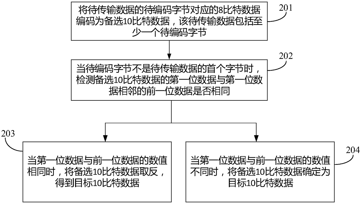
[0005] In order to solve the problem that the existing 8b / 10b encoding method cannot be compatible with PLL and DLL, the embodiment of the present application provides an encoding method, device and display device

Method used


Image

  • Coding method and device and display device
  • Coding method and device and display device
  • Coding method and device and display device

Examples


Embodiment Construction

[0129] In order to make the purpose, technical solutions and advantages of the application clearer, the application will be further described in detail below in conjunction with the accompanying drawings. Obviously, the described embodiments are only some of the embodiments of the application, not all of them. . Based on the embodiments in this application, all other embodiments obtained by persons of ordinary skill in the art without making creative efforts belong to the scope of protection of this application.

[0130] Please refer to figure 1 , figure 1 is a schematic diagram of an application environment of an encoding method provided by an embodiment of the present invention, such as figure 1 As shown, the encoding method is applied to a display device, and the display device includes a controller 01 and a plurality of source driver chips 02, and the plurality of first signal lines H of the controller 01 and the plurality of source driver chips 02 are one by one Corres...


PUM


Abstract

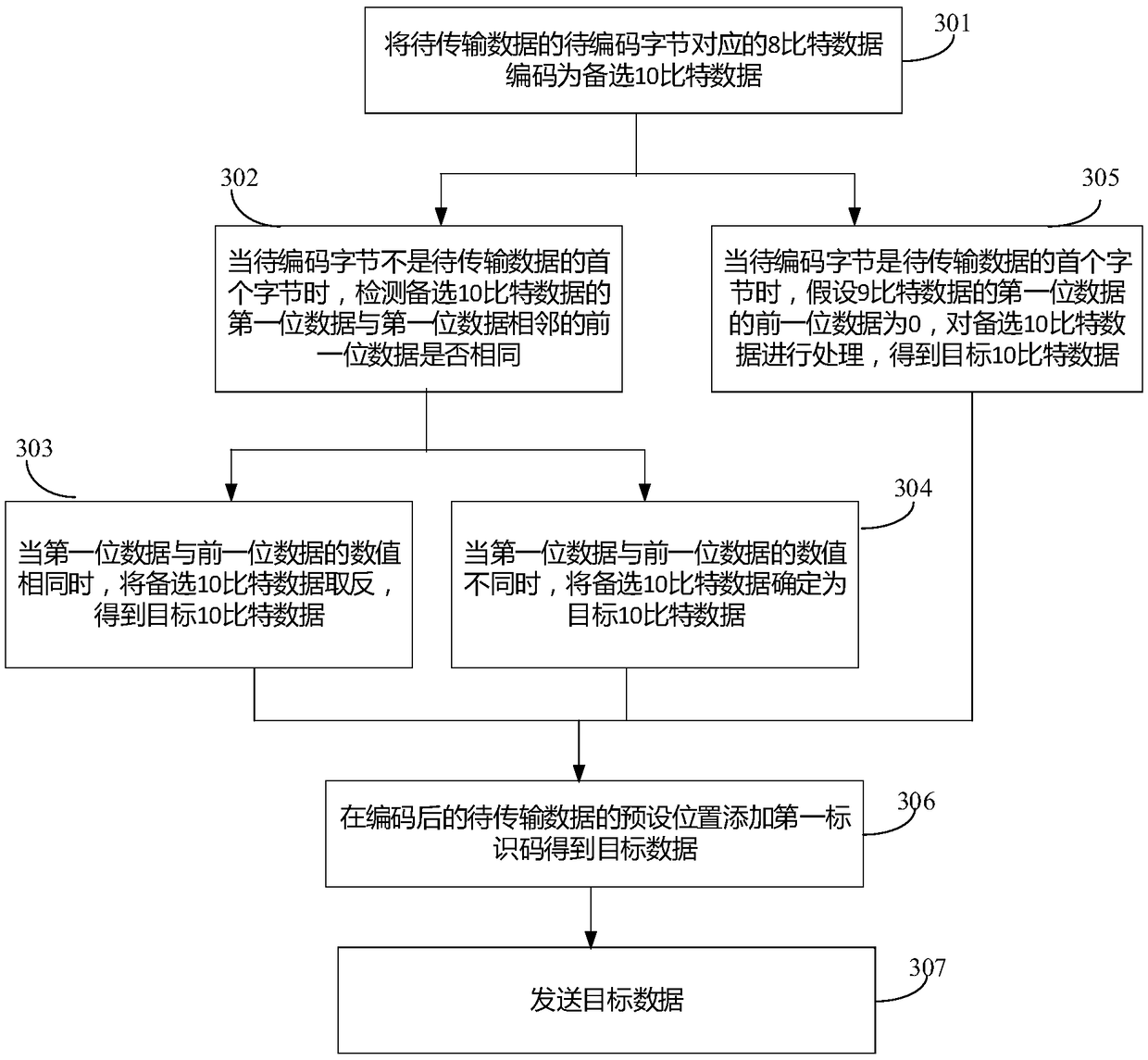
The invention relates to a coding method and device and a display device, belonging to the panel manufacturing field. The method includes: encoding 8-bit data corresponding to bytes to be encoded of data to be transmitted into optional 10-bit data, wherein the data to be transmitted comprises at least one byte to be encoded; when the byte to be encoded is not the first byte of the data to be transmitted, detecting whether the first bit data of the alternate 10-bit data is the same as the first bit data adjacent to the first bit data; when the value of the first bit data is the same as that ofthe previous bit data, inverting the alternate 10-bit data to obtain the target 10-bit data; determining the alternate 10-bit data as target 10-bit data when the first bit data differs from a value ofthe previous bit data, wherein the target 10-bit data is binary data. The present application achieves compatibility of the PLL and the DLL. The present application is for channel coding of a signaltransmission system.

Description

technical field [0001] The present application relates to the field of panel manufacturing, in particular to an encoding method, device and display device. Background technique [0002] The driving part of the liquid crystal display panel usually includes a controller (English Timing Controller), a source driver (English Source Driver) and a gate driver (English Gate Driver), wherein the main function of the controller is to process each frame of image data, A data signal and a control signal corresponding to each frame of image data are generated, and the data signal is transmitted to the source driver, and the source driver converts the received data signal into a data voltage for writing into a corresponding pixel on the liquid crystal display panel. [0003] With the improvement of the resolution of the liquid crystal display panel, the data transmission rate between the controller and the source driver in the liquid crystal display panel is getting higher and higher. At...

Claims


Application Information

Patent Timeline
Patent Type & Authority Applications(China)
IPC IPC(8): G06F3/147G06F3/14G09G3/36G09G3/3208
CPCG06F3/1407G06F3/147G09G3/3208G09G3/36G09G2370/08H04L25/4908H04L25/4915G09G3/2096G09G2310/08H04L25/4906
Inventor 段欣孙伟陈明罗信忠
Owner BOE TECH GRP CO LTD
Learn More