A switch

A switch and button technology, applied in the field of switches, can solve the problems of excessive material consumption, cumbersome assembly steps, uncoordinated switch buttons, etc., and achieves the effects of easy modular use, simple structure, and easy assembly.

Inactive Publication Date: 2019-01-08
马鞍山虹迈专业化设计有限公司
View PDF3 Cites 5 Cited by
  • Summary
  • Abstract
  • Description
  • Claims
  • Application Information

AI Technical Summary

Problems solved by technology

[0007] The purpose of the present invention is to solve the problem of inconsistency between the switch button and the electrical connection between the movable contact and the static contact when the existing switch is electrically connected to the movable contact and the static contact
At the same time, most of the existing technical solutions are assembled through the transfer structure, so that the switch needs to consume excess materials in the production process and the assembly steps are relatively cumbersome, and an easy-to-assemble open-hang structure is provided.

Method used


Image

  • A switch
  • A switch
  • A switch

Examples


Embodiment 1

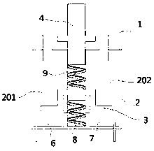
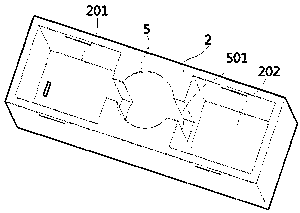
[0081] Such as Figure 1-6 As shown, a switch of this embodiment includes a switch upper case 1, a switch lower case 2 and a switch function part; The element 8, the second elastic element 9 and the installation groove of the static contact piece. The keyway 5 is fixedly arranged in the switch lower case 2 or forms an integral structure with the switch lower case 2 . The bottom surface of the keyway 5 is connected with the inner bottom surface of the switch lower case 2 . The static contacts include incoming line contacts 6 and outgoing line contacts 7 . The incoming line contact piece 6 and the outgoing line contact piece 7 are respectively installed in the corresponding incoming line contact piece installation groove 201 and the outgoing line contact piece installation groove 202 on both sides of the key groove 5 . The movable contact piece 3, the button 4, the first elastic element 8 and the second elastic element 9 are all independently positioned in the keyway 5, and t...

Embodiment 2

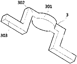
[0090] Such as Figure 7 As shown, a switch in this embodiment has the same structure as the switch main body described in Embodiment 1, the difference is that a raised column structure is provided under the contact stopper 301, and the raised The raised cylinder structure can be inserted into the keyway, and reciprocates up and down in the keyway. The purpose of the column structure provided in this embodiment is to shorten the effective elastic force distance of the first elastic element 8 to the movable contact piece 3, so as to improve the space utilization rate.

Embodiment 3

[0092] Such as Figure 8 As shown, a switch in this embodiment has the same structure as the switch body in any of the embodiments 1-2, the difference is that the hand control part 403 on the button 4 is canceled to form a hole The inner button controls the up and down displacement of the button by inserting an object into the button hole 101, thereby controlling the on-off of the switch.


PUM


Abstract

The switch is provided with a keyway, in which a first spring, a movable contact piece, a second spring and a key are sequentially installed from bottom to top, and two sides of the keyway are provided with an incoming contact piece mounting groove and an outgoing contact piece mounting groove, and the incoming contact piece and the outgoing contact piece are respectively installed in the corresponding groove. As that first spring and the second spring are compress by pressing the key, the movable contact piece is moved downward, so that the incoming contact piece and the outgoing contact piece are connected, and the circuit is connected; Release the key, the first spring bounces and the moving contact moves up, thereby disconnecting the circuit. The switch of the invention is further provided with a plug spring piece and a terminal on the side wall of the switch to realize the modular use of the switch.

Description

technical field [0001] The present invention relates to the field of switches, more specifically, to a switch. Background technique [0002] The key switch used in the prior art includes a key, a movable contact piece and a static contact piece. Pressing the key causes the key body to squeeze the movable contact piece, thereby causing the movable contact piece to move downward. At least one of the moving contact piece and the static contact piece has an elastic structure, and the elastic electrical connection is realized through surface-to-face contact between the moving contact piece and the corresponding static contact piece, so as to realize the switching path. [0003] The publication number is CN108550485A "An Extended Range Key Switch". The invention is an extended range key switch, which includes a casing, a key body, a moving contact piece, a static contact piece, a reset elastic element and an extended range elastic element. The moving contact piece is movably conn...

Claims


Application Information

Patent Timeline
Patent Type & Authority Applications(China)
IPC IPC(8): H01H13/14H01H13/30H01H13/32H01H13/52
CPCH01H13/14H01H13/30H01H13/32H01H13/52H01H2013/525
Inventor 李利
Owner 马鞍山虹迈专业化设计有限公司
Why Eureka
Try Eureka