Cyclone redistribution denitration reactor for flue gas

A denitrification reactor, distributed technology, applied in gas treatment, separation method, dispersed particle separation and other directions, can solve the problems of flue gas distribution dead angle, uneven mixing of ammonia gas, affecting denitration efficiency, etc., to improve the uniformity of mixing, The effect of reducing the probability of blockage and improving efficiency

Active Publication Date: 2019-01-11
ZHEJIANG TUNA ENVIRONMENTAL SCI & TECH
View PDF6 Cites 1 Cited by
  • Summary
  • Abstract
  • Description
  • Claims
  • Application Information

AI Technical Summary

Problems solved by technology

[0005] However, at present, the distribution of flue gas in the denitrification reactor basically adopts the distribution grid in the reactor, which leads to uneven distribution of flue gas in the denitrification re

Method used


Image

  • Cyclone redistribution denitration reactor for flue gas
  • Cyclone redistribution denitration reactor for flue gas
  • Cyclone redistribution denitration reactor for flue gas

Examples


Embodiment Construction

[0045] The present invention will be described in further detail below in conjunction with the accompanying drawings.

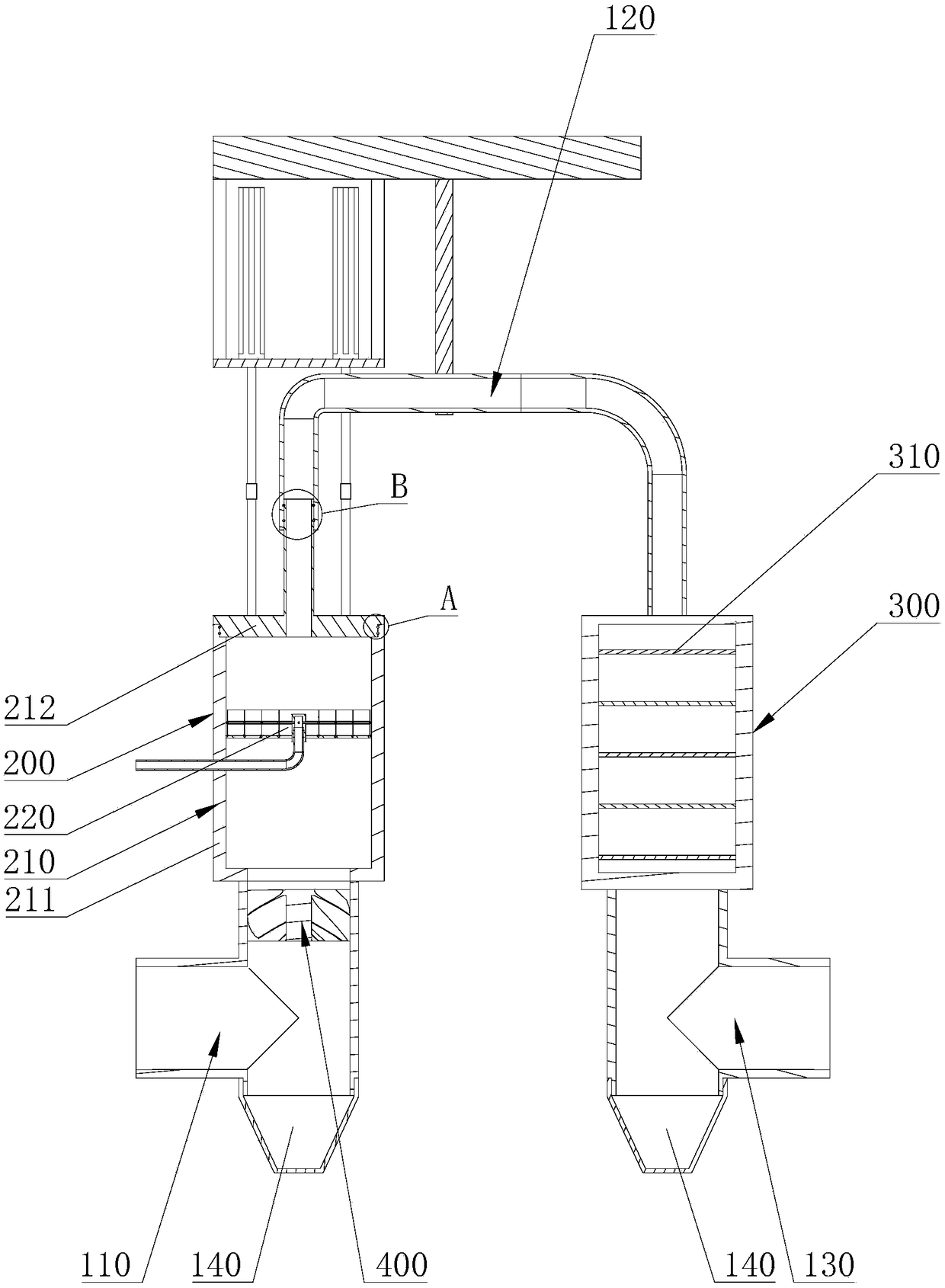
[0046] See attached figure 1 , a flue gas swirling redistributed denitrification reactor, comprising a flue gas inlet pipe 110, an ammonia injection mixing device 200 connected to the flue gas inlet pipe 110, a catalytic reaction device 300, and a catalytic reaction device connected to the ammonia injection mixing device 200 The connecting flue pipe 120 between the devices 300 and the flue gas outlet pipe 130 connected with the catalytic reaction device 300 . The flue gas sequentially passes through the flue gas inlet pipe 110, the ammonia injection mixing device 200, the connecting flue gas pipe 120, and the catalytic reaction device 300, and finally leaves the entire flue gas swirling and distributed denitrification reactor from the flue gas outlet pipe 130, wherein the flue gas The ammonia injection mixing device 200 is mixed with the flue gas, and the mi...


PUM


Abstract

The invention discloses a cyclone redistribution denitration reactor for flue gas in order to solve the technical problem of poor mixing uniformity of flue gas and ammonia gas at present. The cycloneredistribution denitration reactor for flue gas comprises a flue gas inlet tube, an ammonia spraying and mixing device connected with the flue gas inlet tube, a catalytic reaction device, a connectingflue gas tube connected between the ammonia spraying and mixing device and the catalytic reaction device and a flue gas outlet tube connected with the catalytic reaction device, a cyclone device is connected between the flue gas inlet tube and the ammonia spraying and mixing device, the cyclone device comprises an outer cyclone tube, an inner cyclone column and a plurality of arc-shaped flow guiding plates having a spiral curved shape, the plurality of arc-shaped flow guiding plates are circumferentially arranged on the inner cyclone column at intervals and are arranged obliquely, and the outside edges of the flow guiding plates are connected and fixed to the outer cyclone tube. The cyclone device arranged on the cyclone redistribution denitration reactor for flue gas enhances the mixingdegree of ammonia gas and flue gas, so the improvement of the denitration efficiency of the denitration reactor is facilitated.

Description

technical field [0001] The invention relates to an environmental protection device, in particular to a flue gas swirling re-distributed denitrification reactor. Background technique [0002] The control of air pollution is an important part of environmental governance. With the development of industry and the improvement of living standards, people pay more and more attention to environmental issues and atmospheric environmental protection issues. [0003] Nitric oxide is a polluting gas. Nitric oxide is easy to pollute the atmosphere, soil and water after it is directly discharged into the atmosphere. Therefore, when the factory discharges flue gas, especially the exhausted flue gas contains Nitric oxide requires denitrification of the flue gas. Among them, the existing flue gas denitrification technologies mainly include dry method and wet method. Compared with wet flue gas denitrification technology, the main advantages of dry flue gas denitrification technology are: low...

Claims


Application Information

Patent Timeline
IPC IPC(8): B01D53/90B01D53/86B01D53/56
CPCB01D53/8631B01D53/90B01D2258/0283
Inventor 赵博宣学伟陈小利蒋成军汪浩才顾一飞
Owner ZHEJIANG TUNA ENVIRONMENTAL SCI & TECH
Why Eureka
Try Eureka