
Stone impurity roller centrifugal removal device

A centrifugal and drum technology, which is applied in the direction of solid separation, separating solids from solids with airflow, and filtering and sieving, can solve the problems of operating environment pollution, increasing manpower and material investment, and single function, so as to avoid dust. pollution effect

Active Publication Date: 2019-01-11
重庆嘉洲建材有限责任公司
View PDF5 Cites 2 Cited by
  • Summary
  • Abstract
  • Description
  • Claims
  • Application Information

AI Technical Summary

Problems solved by technology

[0002] The stone is broken by a special crusher, which will cause some lime powder, crushed stones and weeds to appear in the stone, and the clean stone can improve the use effect of the stone. The structure of the common stone removal equipment is simple and clumsy. , the single function has the following defects: 1. Ordinary stone material removal equipment usually adopts the vibrating screen type, the stone material is placed on the net frame, and the stone material moves left and right through reciprocating motion, and the impurities inside are separated and fallen to achieve separation. purpose, but these impurities containing crushed stones, weeds and lime powder will be discarded, which cannot achieve the effect of reuse of crushed stones. 2. The lime powder in the impurities will cause dust pollution and pollute the operating environment. 3. Clean up The finished stone is usually loaded with a special machine for secondary loading, which increases the input of manpower and material resources and reduces work efficiency. Therefore, the present invention provides a stone impurity drum centrifugal removal device

Method used


Image

  • Stone impurity roller centrifugal removal device
  • Stone impurity roller centrifugal removal device
  • Stone impurity roller centrifugal removal device

Examples


Embodiment approach

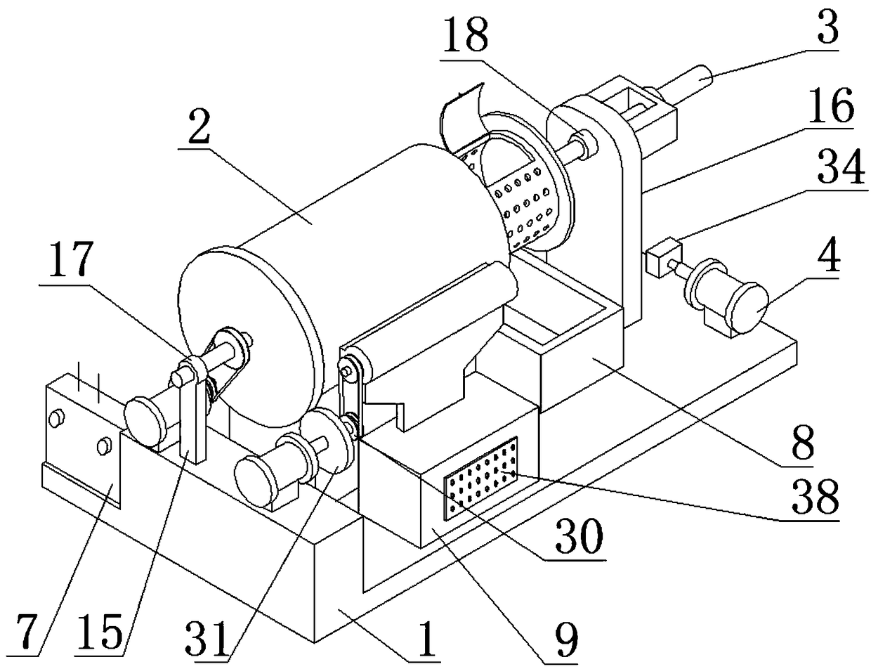
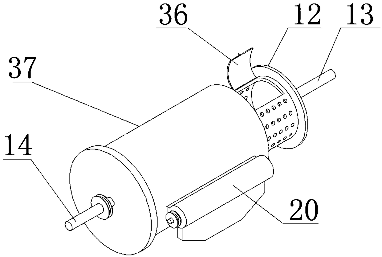
[0033] As a preferred embodiment of the present invention, one side of the centrifugal disc 19 is provided with an annular platform, the annular platform and the centrifugal generating sleeve 37 form a rotary pair, and the inclined blades 42 are arranged inside the annular platform.

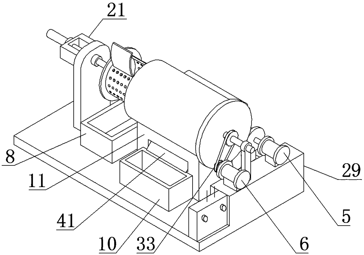
[0034] As a preferred embodiment of the present invention, the passage bracket 11 is provided with a gravel passage 41 , and the dust box 9 is arranged on the horizontal base 1 and corresponds to the gravel passage 41 .

[0035] As a preferred embodiment of the present invention, the bottom of the centrifugal generating sleeve 37 is provided with a filter punching arc plate, and the filter punching arc plate corresponds to the gravel channel 41 .

[0036] As a preferred embodiment of the present invention, the rock trough 8 is arranged on the horizontal base 1 and corresponds to the screen drum 35 .

[0037] As a preferred embodiment of the present invention, an exhaust plate 38 is provided on one ...


PUM


Abstract

The invention discloses a stone impurity roller centrifugal removal device. The impurity roller centrifugal removal device comprises a horizontal base, a filter roller set, a telescopic oil cylinder,a cylinder driving group, a pulse impurity-discharging motor, a low speed roller motor and a control electric box, wherein the horizontal base is provided with a stone trough, a dust box, a large particle box and a channel bracket, and the filter roller set is disposed on the channel bracket. The filter roller set includes a low speed roller and a centrifugal generator sleeve, a rotating shaft isarranged at one end of the low speed roller, and a telescopic rotating shaft set is arranged at the other end of the low speed roller. The horizontal base is provided with a bracket and a supporting sliding plate, the bracket is provided with a first rotating sleeve, and the supporting sliding plate is provided with a second rotating sleeve. The stone impurity roller centrifugal removal device adopts a composite roller horizontal structure, the low speed drum rotates at a low speed, large particle impurities directly fall into the large particle box at the bottom, a centrifugal disk rotating at a high speed generates centrifugal air between the low speed roller and the centrifugal generator sleeve, and weeds, light stone powder and stone can be separated.

Description

technical field [0001] The invention relates to the field of stone impurity removal, in particular to a stone impurity drum centrifugal removal device. Background technique [0002] The stone is broken by a special crusher, which will cause some lime powder, crushed stones and weeds to appear in the stone, and the clean stone can improve the use effect of the stone. The structure of the common stone removal equipment is simple and clumsy. , the single function has the following defects: 1. Ordinary stone material removal equipment usually adopts the vibrating screen type, the stone material is placed on the net frame, and the stone material moves left and right through reciprocating motion, and the impurities inside are separated and fallen to achieve separation. purpose, but these impurities containing crushed stones, weeds and lime powder will be discarded, which cannot achieve the effect of reuse of crushed stones. 2. The lime powder in the impurities will cause dust poll...

Claims


Application Information

Patent Timeline
Patent Type & Authority Applications(China)
IPC IPC(8): B07B1/24B07B1/42B07B1/46B07B7/083B07B9/00B07B11/06B07B11/04
CPCB07B1/24B07B1/42B07B1/46B07B7/083B07B9/00B07B11/04B07B11/06
Inventor 朱静轩
Owner 重庆嘉洲建材有限责任公司
Learn More