Drive unit for hoist

A driving device, elevator technology, applied in the direction of hoisting device, transportation and packaging, spring mechanism, etc., to achieve the effect of reducing the length of the structure, reducing the cost, and reducing the length of the drive shaft

Inactive Publication Date: 2002-10-02
WITTUR
View PDF2 Cites 4 Cited by
  • Summary
  • Abstract
  • Description
  • Claims
  • Application Information

AI Technical Summary

Problems solved by technology

The solution proved to be successful, but the compact and possibly extremely compact installation proc...

Method used


Image

  • Drive unit for hoist
  • Drive unit for hoist
  • Drive unit for hoist

Examples


Embodiment Construction

[0016] Detailed Description of Preferred Embodiments

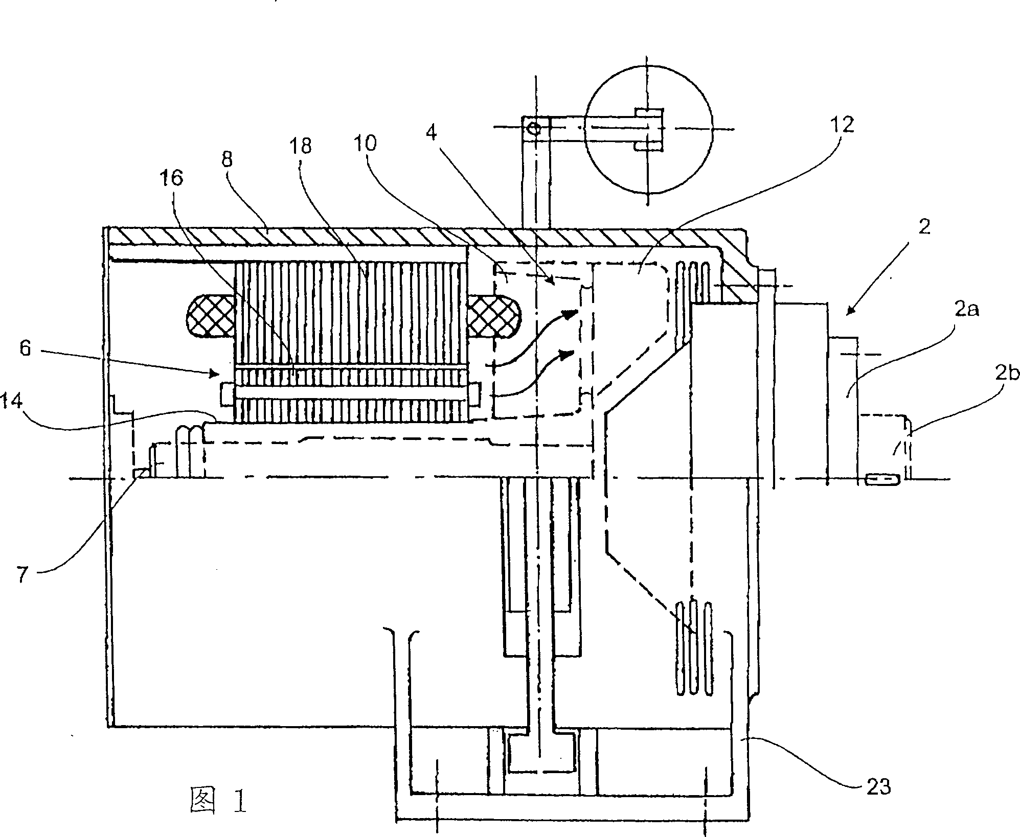
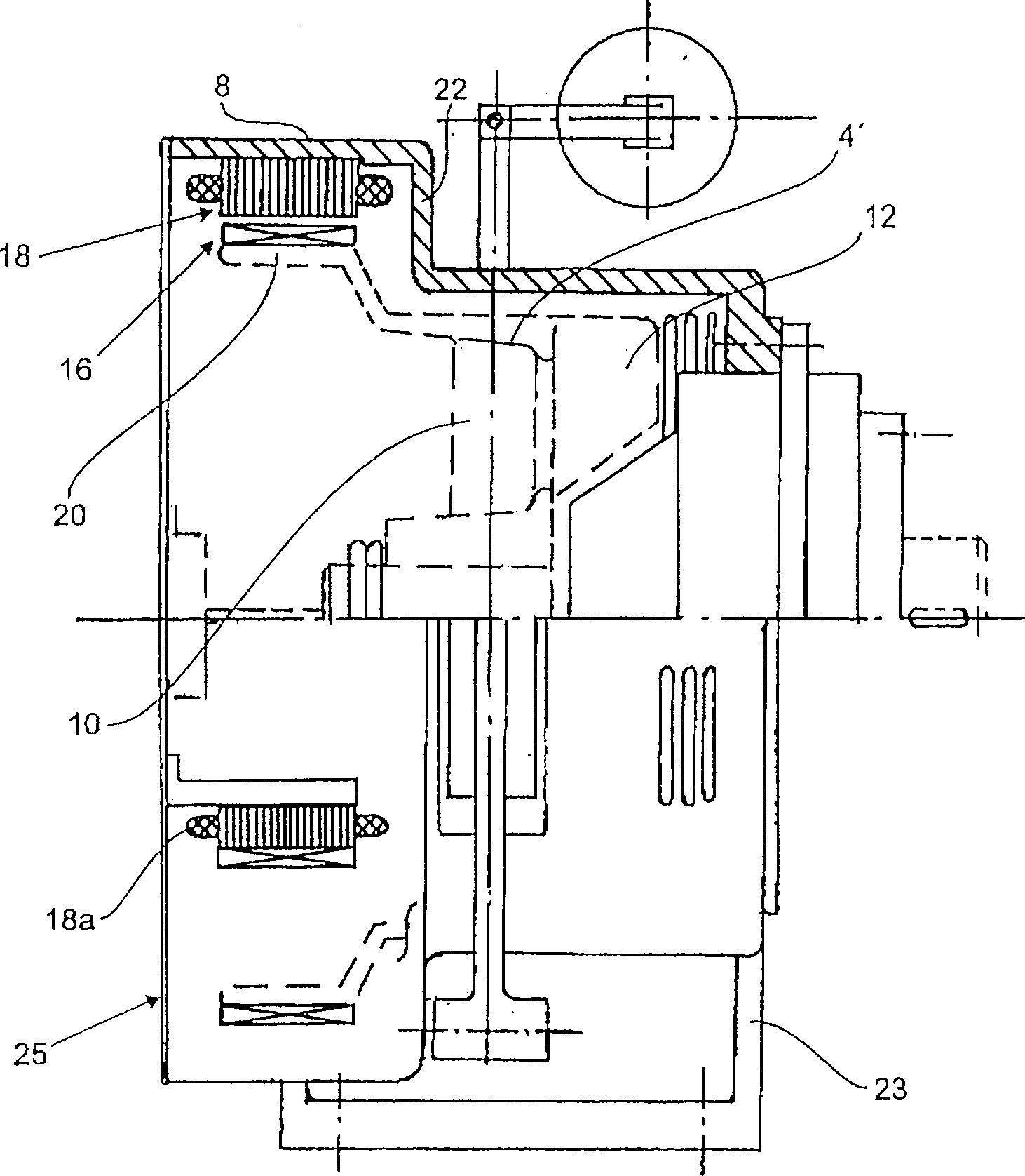
[0017] FIG. 1 is a schematic diagram of a driving device of an elevator. The basic components include a transmission device 2 , a brake 4 and a motor 6 , which are coaxially mounted on a drive shaft 7 . The casing 8 contains the brake 4, the motor 6 and a part of the transmission device, and carries an elevator cable drive disc (not shown in the figure). The casing 8 is anchored on a foundation (not shown). The drive disk can be supported or mounted on the drive flange 2a or on the drive shaft 2b.

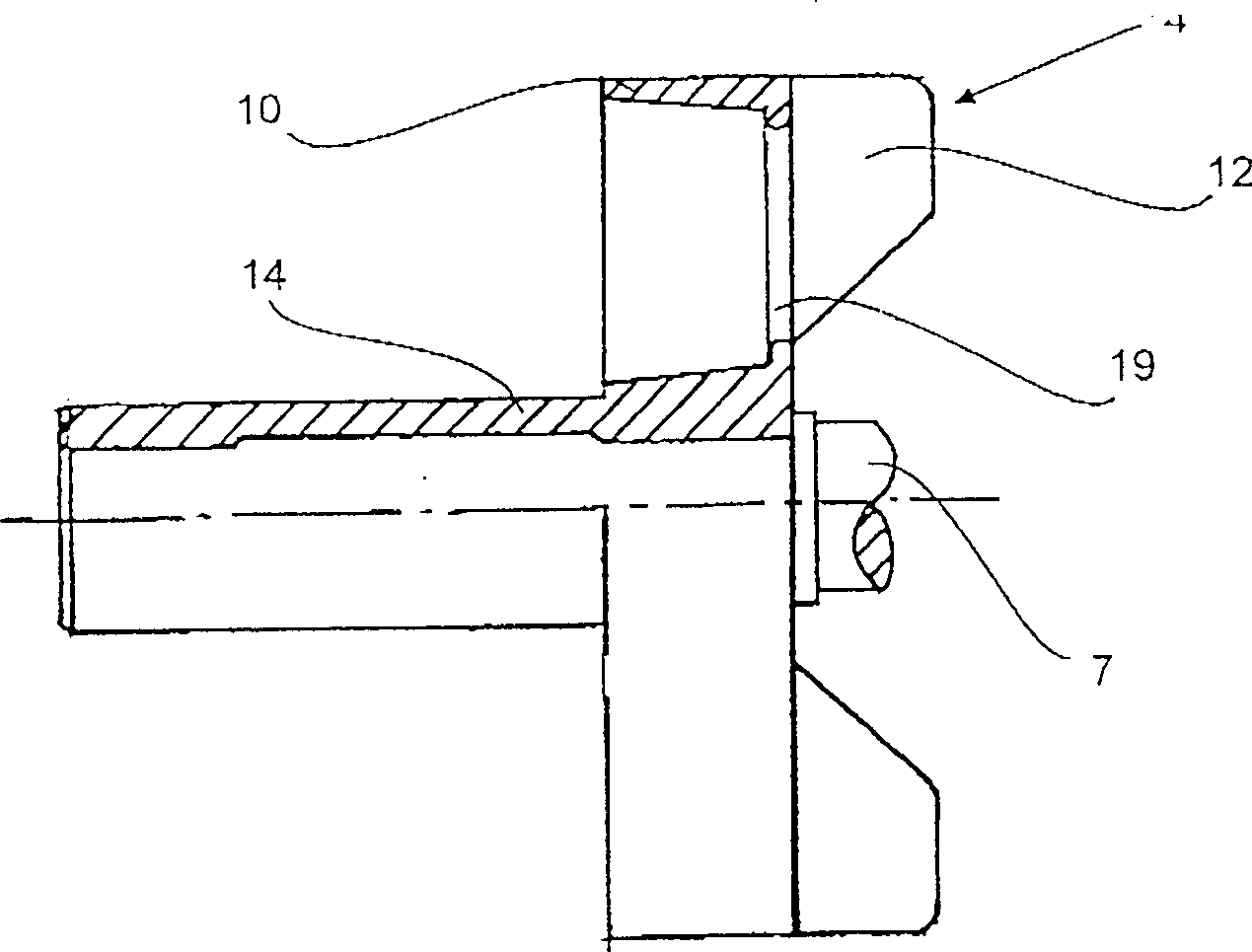
[0018] Described brake 4 has the brake body 10 of a cast brake drum shape, is provided with the rotor bushing 14 of the rotor 16 of ventilation vane 12 and described motor 6 (having rotor 16 and stator 18) on it (see also Figure 3a ). The stator winding is coupled with the brake drum 4 (used as a motor output), and the brake drum, for example, can be provided with vents 19 on the axially outer surface of the brake drum ( ...


PUM


Abstract

The drive device comprises a motor (6), a gearbox (2), a brake device (4) and a housing (8). The motor and the brake device are accommodated together in the housing. In the housing, part of the gearbox is located as an extension gearbox or adapter gearbox so that the housing also forms the gearbox housing. The brake has a brake body defined by a drum (10) on which fan blades and/or a rotor sleeve are located. The brake drum and the rotor sleeve are designed as one-piece shapes and castings.

Description

technical field [0001] The invention relates to a driving device of a crane, in particular to a driving device of an electric lift with a motor, a transmission device, a brake device and a casing. Background technique [0002] Such a drive is to be found in EP 706 968, which discloses a drive which is structurally simple, has a small overall length and generates low inertial forces. The motor and transmission device can be fixed on the flange of the brake housing in the form of a cantilever beam, and the brake housing acts as a stator and becomes the only component that needs to be fixed on the foundation, that is, the base. This solution has proven to be successful, but the compact and possibly extremely compact installation process of assembling the drive and / or installing it into the hoist creates the need for further structural simplification. The present invention attempts to solve this problem. Contents of the invention [0003] In order to solve the above problems...

Claims


Application Information

Patent Timeline
IPC IPC(8): B66D1/02B66B11/08B66B11/04
CPCB66B11/043
Inventor 胡伯特·菲舍尔
Owner WITTUR
Why Eureka
Try Eureka