3D printing machine forming platform lifting mechanism

A 3D printer, platform lifting technology, used in 3D object support structures, processing platforms/substrates, additive manufacturing, etc.

Inactive Publication Date: 2019-01-11
赵自文
View PDF1 Cites 1 Cited by
  • Summary
  • Abstract
  • Description
  • Claims
  • Application Information

AI Technical Summary

Problems solved by technology

[0002] For example, the self-elevating platform lifting mechanism and the self-elevating platform whose patent number is CN201120471468.0 include: the lifting mechanism body; the driving motor, which is arranged on one side of the lifting mechanism body; the planetary reduction box, which is located at the lifting mechanism body The lower part of the lower part; the parallel shaft reduction box, which is arranged between the driving motor and the planetary reduction box; the brake, which is separated from the driving motor and connected with the driving motor; and the climbing gear, which is connected with the driving motor The racks of the legs of the platform are meshed, wherein the drive motor drives the climbing gear through the parallel shaft gearbox and the planetary gearbox in turn, and this design has no clamping device for clamping the processed material

Method used


Image

  • 3D printing machine forming platform lifting mechanism
  • 3D printing machine forming platform lifting mechanism
  • 3D printing machine forming platform lifting mechanism

Examples


specific Embodiment approach 1

[0045] Combine below Figure 1-20 To describe this embodiment,

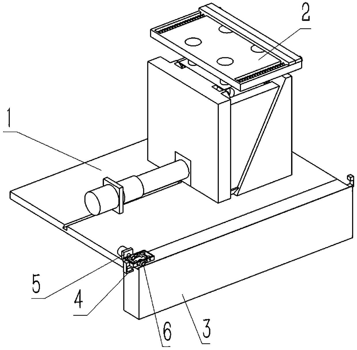
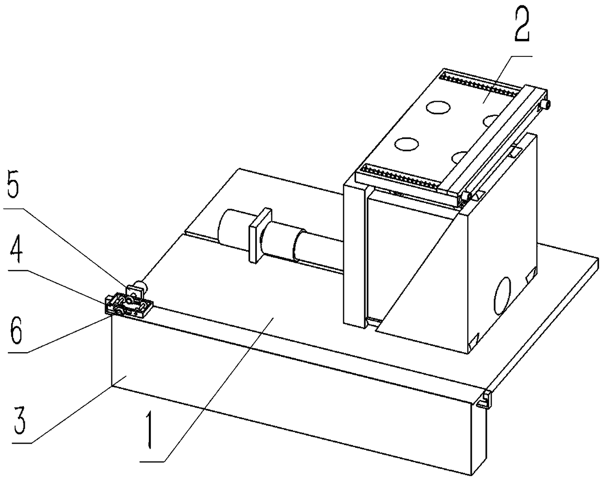
[0046] A 3D printer forming platform lifting mechanism, including a frame body 1, a lifting platform combination 2, an outer sliding frame 3, a reversing combination 4, a motor combination 5 and a transmission combination 6, and the lifting platform combination 2 is slidably connected to the frame body 1, the right end of the frame body 1 is slidably connected to the outer sliding frame 3, the reversing combination 4 is connected between the outer sliding frame 3 and the motor combination 5, and the left and right ends of the transmission combination 6 are respectively connected to the motor combination 5 and the outer Slide frame 3 engages the transmission.

specific Embodiment approach 2

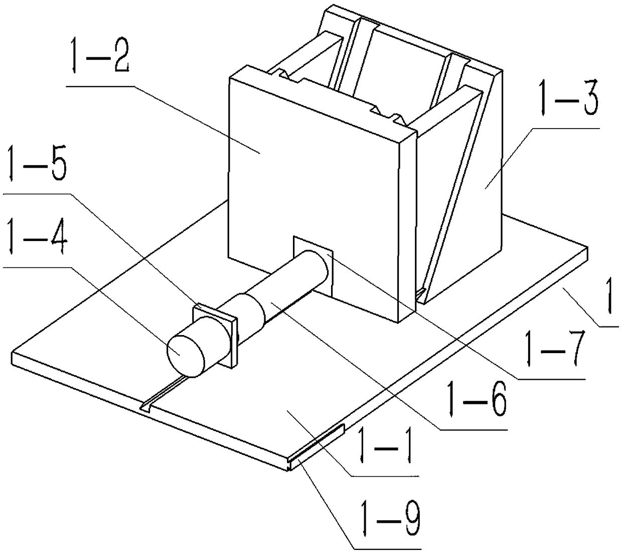
[0047] Combine below Figure 1-20 This embodiment will be described. This embodiment will further describe the first embodiment. The frame body 1 includes a bottom plate 1-1, a front frame body 1-2, a rear frame body 1-3, a motor 1-4, and a machine base 1- 5. Screw rod 1-6, positioning block 1-7, end 1-8 and trapezoidal slider 1-9, the upper end of the bottom plate 1-1 is provided with a trapezoidal groove 1-1-1, and the front frame body The lower end of 1-2 is connected to the base plate 1-1 by bolts, the lower end of the rear frame body 1-3 is in clearance fit with the upper end surface of the base plate 1-1, and the front frame body 1-2 is slidingly connected between the rear frame body 1-3 Inside, the motor 1-4 is fixed on the machine base 1-5 by bolts, the lower end of the machine base 1-5 is slidingly connected in the trapezoidal groove 1-1-1, and the drive shaft of the motor 1-4 is connected to the wire through a coupling. The front end of the rod 1-6, the positioning ...

specific Embodiment approach 3

[0050] Combine below Figure 1-20 Describe this embodiment, this embodiment will further explain the second embodiment, the lifting platform combination 2 includes a lower support platform 2-1, a runner 2-2, an upper support platform 2-3, bolts 2-4 and nuts 2 -5, four runners 2-2 are provided, and the four runners 2-2 are respectively rotated and connected to the four corners of the lower support platform 2-1, four nuts 2-5 are provided, and the upper support platform 2- 3 connected to the upper end of the lower support platform 2-1 by bolts 2-4;

[0051] The upper support platform 2-3 includes an upper support platform body 2-3-1, a slider 2-3-2, a lock nut 2-3-3 and a spring 2-3-4, and the upper support platform body 2 The upper end of -3-1 is provided with four threaded holes 2-3-1-1, and the left and right sides of the upper support platform body 2-3-1 are respectively provided with a trapezoidal groove 2-3-1-2, so A sliding post 2-3-1-3 is welded in the trapezoidal groo...


PUM


Abstract

The invention relates to a platform lifting mechanism, in particular to a 3D printing machine forming platform lifting mechanism which can achieve automatic platform lifting, clamp machining materialsand adjust the using position of the platform. The 3D printing machine forming platform lifting mechanism comprises a machine frame body, a lifting platform assembly, an outer side slide frame, a reversing assembly, a motor assembly and a transmission assembly; the lifting platform assembly is slidably connected to the upper end of the machine frame body; the right end of the machine frame body is slidably connected to the outer side slide frame; the reversing assembly is connected between the outer side slide frame and the motor assembly; the left end and the right end of the transmission assembly are in engagement transmission with the motor assembly and the outer side slide frame; a motor in the machine frame body can drive a screw rod to transmit, and circular motion of the screw rodis converted into linear motion of the device; a lower supporting platform and a rotation wheel which are in the lifting platform assembly cooperate with a front frame body and a rear frame body, andvertical motion of the device is achieved; and through the lifting platform assembly, the machining materials can be clamped between two sliders.

Description

technical field [0001] The invention relates to a platform lifting mechanism, more specifically, a 3D printer forming platform lifting mechanism. Background technique [0002] For example, the self-elevating platform lifting mechanism and the self-elevating platform whose patent number is CN201120471468.0 include: the lifting mechanism body; the driving motor, which is arranged on one side of the lifting mechanism body; the planetary reduction box, which is located at the lifting mechanism body The lower part of the lower part; the parallel shaft reduction box, which is arranged between the driving motor and the planetary reduction box; the brake, which is separated from the driving motor and connected with the driving motor; and the climbing gear, which is connected with the driving motor The racks of the legs of the platform are meshed, wherein the drive motor drives the climbing gear through the parallel shaft gearbox and the planetary gearbox in turn, and this design has...

Claims


Application Information

Patent Timeline
IPC IPC(8): B29C64/232B29C64/245B33Y30/00
CPCB29C64/245B29C64/232B33Y30/00
Inventor 赵自文
Owner 赵自文
Why Eureka
Try Eureka