Supercharge Your Innovation With Domain-Expert AI Agents!

Pneumatic conveying equipment

A pneumatic conveying and equipment technology, which is applied in the field of material conveying, can solve the problems of operation fatigue and low adjustment accuracy, and achieve the effects of reducing pressure loss, long spraying distance and wide range of applicable working conditions

Pending Publication Date: 2019-01-11
常州泰聚环保科技有限公司
View PDF0 Cites 1 Cited by
  • Summary
  • Abstract
  • Description
  • Claims
  • Application Information

AI Technical Summary

Problems solved by technology

[0004] The technical problem to be solved by the present invention is: in order to solve the technical problems of low adjustment accuracy of the pneumatic conveying equipment in the prior art and easy to cause operational fatigue during the debugging process, the present invention provides a pneumatic conveying equipment to solve the above problems

Method used


Image

  • Pneumatic conveying equipment
  • Pneumatic conveying equipment
  • Pneumatic conveying equipment

Examples


Embodiment Construction

[0030] Embodiments of the present invention are described in detail below, examples of which are shown in the drawings, wherein the same or similar reference numerals designate the same or similar elements or elements having the same or similar functions throughout. The embodiments described below by referring to the figures are exemplary only for explaining the present invention and should not be construed as limiting the present invention.

[0031] In the description of the present invention, it should be noted that unless otherwise specified and limited, the term "connection" should be understood in a broad sense, for example, it can be a fixed connection, a detachable connection, or an integral connection; It can be a mechanical connection or an electrical connection; it can be a direct connection or an indirect connection through an intermediary. Those of ordinary skill in the art can understand the specific meanings of the above terms in the present invention in specific...


PUM


Abstract

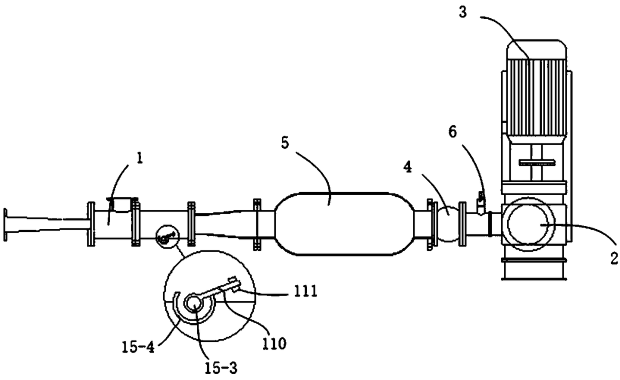
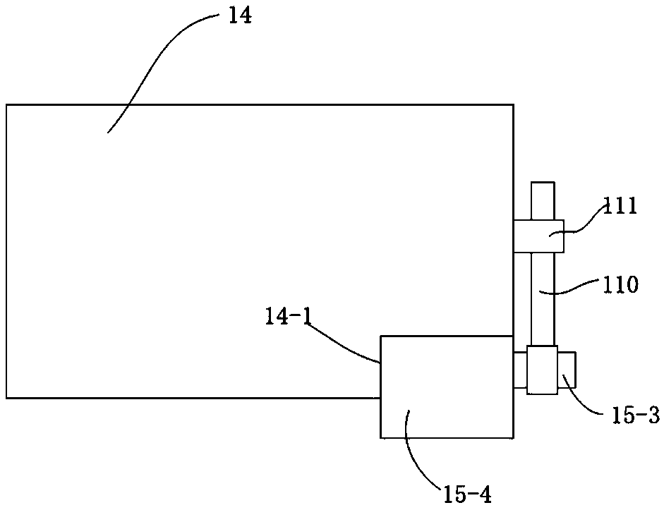
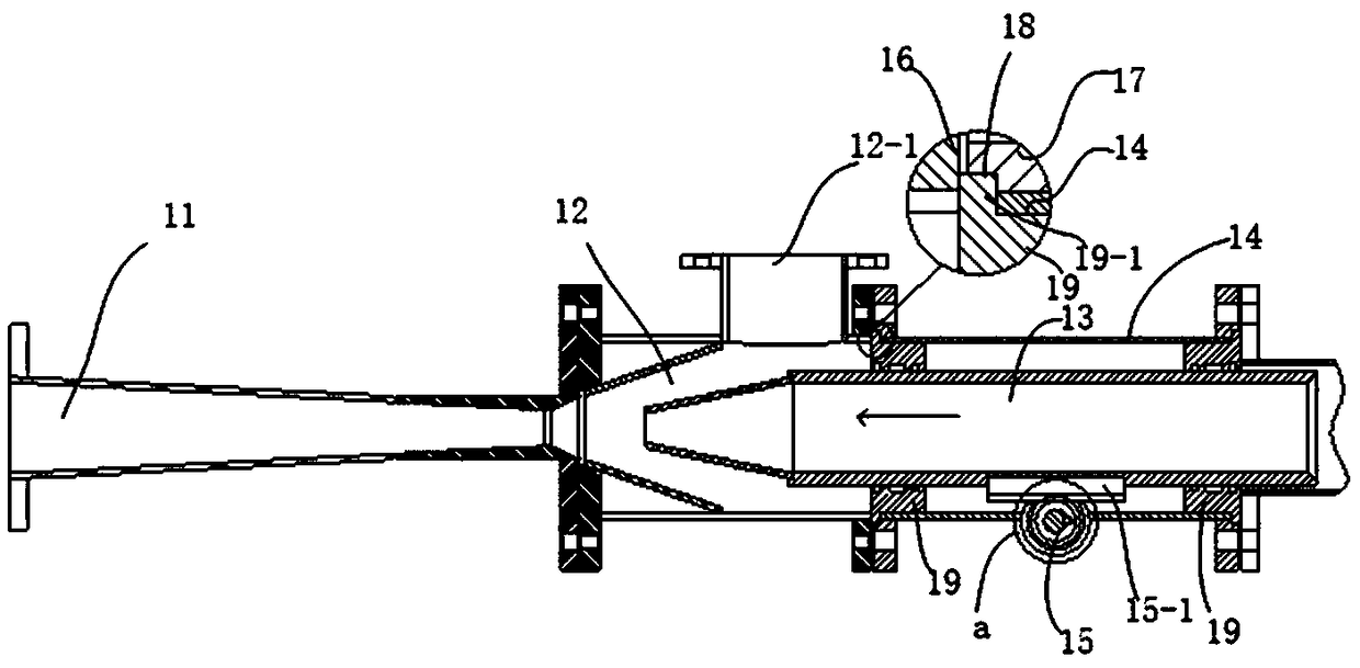
The invention provides pneumatic conveying equipment. The pneumatic conveying equipment comprises a spraying pump, a Roots fan, a soft connecting pipe and a buffer tank; the spraying pump comprises anozzle, a pump body, a wind pipe, a square box and a driving device; the driving device is in transmission connection with the wind pipe for adjusting relative positions of the wind pipe and the nozzle in a spraying direction, and comprises a rack fixed on the wind pipe and gear engaged with the rack; a notch is formed in the side wall of the square box; a gear base is fixed in the notch; a rotating shaft sleeves the center of the gear; and the rotating shaft is erected on the gear base. In the pneumatic conveying equipment, through twice boosting processes of working air currents by the buffer tank and the nozzle, materials are sprayed out under a larger pressure difference, so that the spraying distance is farther; meanwhile, the distance from the wind pipe to the nozzle is adjusted by using the gear; through rotation of the rotating shaft, the tiny displacement of the wind pipe can be realized; and compared with direct linear operation, the rotating operation is easier and higher inprecision.

Description

technical field [0001] The invention relates to the field of material conveying, in particular to a pneumatic conveying device. Background technique [0002] Pneumatic conveying equipment uses the flow of working fluid to form a negative pressure near the outlet of the jet pump. The conveyed object is sucked under the action of negative pressure and flows to the outlet with the working fluid, and then sprays outward through the flared nozzle together. Transport the conveyed goods to the destination. A jet pump generally includes a pump body, a nozzle and an air duct. A negative pressure is formed in the mixing chamber at the transition between the nozzle and the air duct. The passage of the working fluid is a flared structure, the flow rate of the working fluid decreases, the pressure rises gradually, and it is sprayed out together with the conveyed material and enters the conveying pipeline. The size of the mixing chamber has an effect on the pressure and speed of the conv...

Claims


Application Information

Patent Timeline
IPC IPC(8): B65G53/16
CPCB65G53/16
Inventor 孙正奇唐庆荣
Owner 常州泰聚环保科技有限公司
Features
  • R&D
  • Intellectual Property
  • Life Sciences
  • Materials
  • Tech Scout
  • Unparalleled Data Quality
  • Higher Quality Content
  • 60% Fewer Hallucinations
Learn More