Preparation method and application of core-shell type iron-carbon microelectrolysis material high-efficiency Fenton Catalyst

An iron-carbon micro-electrolysis and catalyst technology, applied in chemical instruments and methods, oxidized water/sewage treatment, special compound water treatment, etc., can solve the problems of affecting the effect and efficiency of wastewater treatment, loss of function, heavy workload, etc., to achieve Good micro-electrolysis reaction effect, simple preparation method, and high current density effect

Active Publication Date: 2019-01-11
RES CENT FOR ECO ENVIRONMENTAL SCI THE CHINESE ACAD OF SCI
View PDF4 Cites 10 Cited by
  • Summary
  • Abstract
  • Description
  • Claims
  • Application Information

AI Technical Summary

Problems solved by technology

[0003] Traditionally, the micro-electrolysis materials used in the micro-electrolysis process are generally iron filings and charcoal, which need to be activated with acid and alkali before use. During the use, it is easy to passivate and harden, and because iron and charcoal are in physical contact, it is easy to form a bond between them. The isolation layer prevents micro-electrolysis from continuing and loses its function, which leads to frequent replacement of micro-electrolysis materials, which not only has a large workload and high cost, but also affects the treatment effect and efficiency of wastewater
In addition, the small surface area of ​​traditional micro-electrolysis materials also makes wastewater treatment take a long time, increasing the investment cost per ton of water, which seriously affects the utilization and promotion of micro-electrolysis processes

Method used


Image

  • Preparation method and application of core-shell type iron-carbon microelectrolysis material high-efficiency Fenton Catalyst
  • Preparation method and application of core-shell type iron-carbon microelectrolysis material high-efficiency Fenton Catalyst
  • Preparation method and application of core-shell type iron-carbon microelectrolysis material high-efficiency Fenton Catalyst

Examples


Embodiment 1

[0039] Example 1 : The preparation method of core-shell type Fe-Pd / C composite Fe-C microelectrolytic material of the present invention

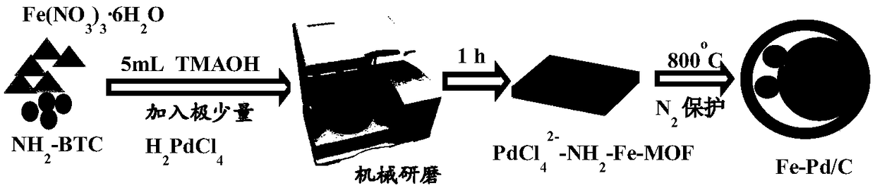
[0040] The synthesizing schematic diagram of the core-shell formula Fe-Pd / C composite Fe-C micro-electrolytic material provided by the present invention is as follows figure 1 Shown, its specific preparation method is:

[0041] First, weigh a certain amount of FeCl 3 , sodium tetrachloropalladate and 2-aminoterephthalic acid are added to the zirconia grinding tank, then a certain volume of tetramethylammonium hydroxide solution and 3-4 zirconia grinding balls are added, and the Grinding at a speed of 0.5-2h to obtain Fe-MOFs-PdCl 2 - Materials; the prepared Fe-MOFs-PdCl 2 - Heating at 800° C. for 2 hours under the protection of nitrogen to obtain a core-shell Fe-Pd / C composite Fe-C micro-electrolytic material.

Embodiment 2

[0042] Example 2 : Structural characterization of the core-shell Fe-Pd / C composite Fe-C microelectrolytic material of the present invention

[0043] This embodiment is the structural characterization of the core-shell Fe-Pd / C composite Fe-C micro-electrolytic material, specifically as follows:

[0044] 1.TEM

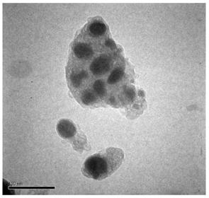
[0045] The particle size and morphology of Fe-Pd / C composite Fe-C micro-electrolytic materials were analyzed by transmission electron microscope H7500 (Hitachi, Japan).

[0046] From figure 2 It can be seen that Fe 0 - The particle size of the Pd nanoparticles is 15-30nm, and the thickness of the carbon shell is about 5nm. core-shell Fe 0 -Pd / C embedded in a large amount of graphitized carbon, increasing the core Fe 0 - Stability of Pd.

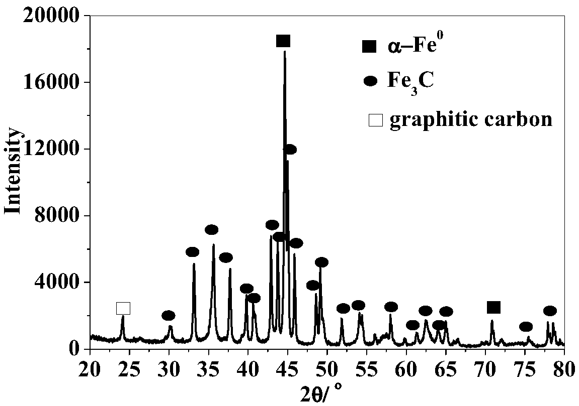
[0047] 2. XRD spectrum

[0048] Fe-MOFs-PdCl prepared by milling method 2 - The X-ray diffraction (XRD) pattern of Fe-Pd / C composite Fe-C microelectrolytic material is obtained on b / max-RB Diffractometer (Rigaku, Japan), usi...

Embodiment 3

[0062] Example 3 : Catalytic performance test of core-shell Fe-Pd / C composite Fe-C micro-electrolytic material of the present invention

[0063] In this example, phenol was selected as a representative, and the catalytic performance of the Fe-Pd / C composite Fe-C micro-electrolytic material was tested.

[0064] The operation steps of the test are as follows: prepare 50 mL of 50 mg / L phenol standard substance, place it in a 100 mL polyethylene plastic vial, add 25 mg of Fe-Pd / C composite Fe-C micro-electrolytic material to make the catalyst concentration 0.5 g / L, and then Add a certain concentration of H 2 o 2 . Shake in a shaker, take 1mL samples at intervals, centrifuge and take the supernatant, respectively for phenol, TOC and Fe 2 + and H 2 o 2 determination. Phenol was measured by HPLC-UV, TOC was detected by TOC / TN analyzer, Fe 2+ and H 2 o 2 Measured with a UV-Vis spectrophotometer.

[0065] The conditions of HPLC-UV method determination are as follows:

[0...


PUM

PropertyMeasurementUnit
diameteraaaaaaaaaa
diameteraaaaaaaaaa
particle diameteraaaaaaaaaa

Abstract

The invention provides a core-shell type iron-carbon microelectrolysis (Fe-Pd/C) nanocatalyst for catalytically degrading high-toxicity organic pollutants in an environmental water sample, and a preparation method thereof. The catalyst is derived from an iron metal-organic framework material (Fe-MOFs). The Fe-MOFs material is prepared by a mechanochemical technology, and undergoes high-temperaturecarbonization to form the core-shell Fe-C microelectrolysis material composed of a graphitized carbon shell (C), zero-valent iron (Fe<0>) and a nano-palladium composite material. A zero-valent iron anode of the core-shell Fe-Pd/C continuously transports electrons to a carbon cathode and releases Fe<2+> in a water sample; the protection of the carbon shell prevents a product obtained after the hydrolysis of iron ions in the solution from adhering to the surface of the zero-valent iron, so a micro-electrolysis reaction is not affected; and nano-palladium particles in the core can promote the conversion of Fe<3+>/Fe<2+> and the pH value of the surface of the catalyst, so a Fenton reaction can be carried out in a pH range of 3-6. The catalyst has a good stability, and can be reused many times, and is very suitable for removing phenol and other pollutants in the environmental water samples by an advanced oxidation technology Fenton reaction.

Description

technical field [0001] The invention belongs to the technical field of highly toxic pollutant treatment, and relates to the large-scale preparation of a core-shell type iron-carbon micro-electrolysis nanometer material and its application as a Fenton catalyst to degrade pollutants. Background technique [0002] Micro-electrolysis technology is currently an ideal process for treating high-concentration organic wastewater, also known as internal electrolysis. It uses the micro-electrolytic material filled in the wastewater to generate a 1.2V potential difference to electrolyze the wastewater to degrade organic pollutants without electricity. During the reaction, nascent Fe was produced at the metal anode 2+ , Atomic H is generated at the carbon cathode. They have high chemical activity and can change the structure and characteristics of many organic substances in wastewater, causing chain scission and ring opening of organic substances. However, the reduction of iron-carbon ...

Claims


Application Information

Patent Timeline
Patent Type & Authority Applications(China)
IPC IPC(8): C02F1/461C02F1/72C02F101/30C02F101/34
CPCC02F1/46109C02F1/46176C02F1/722C02F1/725C02F2001/46142C02F2101/30C02F2101/345C02F2305/026
Inventor 蔡亚岐牛红云何东伟
Owner RES CENT FOR ECO ENVIRONMENTAL SCI THE CHINESE ACAD OF SCI
Why Eureka
Try Eureka