A snap-in raise drilling rig

A raise drilling rig, clip-on technology, applied in construction and other directions, can solve the problems of angle adjustment, wear, damage, etc., and achieve the effect of improving efficiency and floating stability

Active Publication Date: 2020-11-24
JIANGSU HEXIN PETROLEUM MACHINERY
View PDF18 Cites 0 Cited by
  • Summary
  • Abstract
  • Description
  • Claims
  • Application Information

AI Technical Summary

Problems solved by technology

The drill bit in the raise drilling rig is the most important part of the whole mechanism. Generally, the drill bit includes a cutter head, a tool seat, and a hob. The tool seat is installed on the cutter head, and the hob is installed on the tool seat. The distribution and structure of the hob It has a great impact on the efficiency and stability of rock breaking. The existing hob has an integrated cylindrical structure, and grinding ribs are distributed on the side of the cylindrical structure. However, such an integrated hob will be damaged after long-term operation. Impact damage or severe wear, so the entire hob is scrapped, and the hob needs to be disassembled and reinstalled as a whole, which affects operating efficiency and operating costs; the angle of the hob in the prior art cannot be adjusted according to the rock breaking surface. Adjustment, resulting in inconsistent contact between the hob and the rock-breaking surface, resulting in low rock-breaking efficiency

Method used


Image

  • A snap-in raise drilling rig
  • A snap-in raise drilling rig
  • A snap-in raise drilling rig

Examples


Embodiment Construction

[0020] The content of the present invention will be further described in detail below in conjunction with the accompanying drawings.

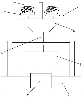
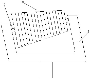
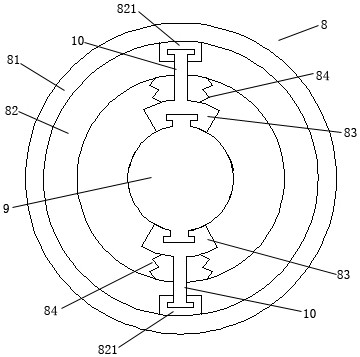
[0021] like Figures 1 to 6 As shown, a clamping type raise drilling machine includes a base support 1, a telescopic mechanism 2, a drill pipe 4, a drill bit 5, and a T-shaped telescopic rod 10; the telescopic mechanism 2 is installed on the base support 1; the described The drill rod 4 is installed on the upper end of the telescopic mechanism 2; the drill bit 5 is installed on the upper end of the drill rod 4; the drill bit 5 includes a cutter head 6, a knife seat 7, a drill bit 8, and a connecting shaft 9; The disk 6 is installed on the upper end of the drill rod 4; the upper end of the cutter head 6 is equipped with two tool holders 7; a connecting shaft 9 is installed in the described cutter holder 7; on axis 9; if image 3 and 4 As shown, it also includes a T-shaped telescopic rod 10; the drill bit 8 includes an outer ring sleeve 81, an...


PUM


Abstract

The invention discloses a clamping type raise boring machine. The clamping type raise boring machine includes a base support, a telescopic mechanism, a drilling rod and a drilling bit. A telescopic groove and a connecting channel are respectively disposed at upper and lower sides of an inner ring sleeve, one end of the T-shaped telescopic rod sequentially passes through a telescopic groove and theconnecting channel and is then fixed on an outer side surface of a clamping plate, the other end of the T-shaped telescopic rod is limited in the telescopic groove, upper and lower ends of a connecting shaft are respectively inserted into T-shaped insertion clamping grooves of the clamping plate through T-shaped insertion clamping bars, so an outer ring sleeve and the inner ring sleeve can move up and down along the T-shaped telescopic rod. The clamping type raise boring machine is advantaged in that floating is more stable.

Description

technical field [0001] The invention relates to a clamping type raise drilling machine. Background technique [0002] At present, raise drilling rigs are mainly used in industries such as vertical shafts, inclined shafts, surge shafts, ventilation shafts and drainage shafts in hydropower projects, ventilation shafts in railway construction, and mine slag shafts. The drill bit in the raise drilling rig is the most important part of the whole mechanism. Generally, the drill bit includes a cutter head, a tool seat, and a hob. The tool seat is installed on the cutter head, and the hob is installed on the tool seat. The distribution and structure of the hob It has a great impact on the efficiency and stability of rock breaking. The existing hob has an integrated cylindrical structure, and grinding ribs are distributed on the side of the cylindrical structure. However, such an integrated hob will be damaged after long-term operation. Impact damage or severe wear, so the entire ho...

Claims


Application Information

Patent Timeline
Patent Type & Authority Patents(China)
IPC IPC(8): E21B10/43E21B10/633
CPCE21B10/43E21B10/633
Inventor 赵钧羡丁扬扬丁跃翔王晓鹏
Owner JIANGSU HEXIN PETROLEUM MACHINERY
Why Eureka
Try Eureka