
Hydraulic oil cylinder

A hydraulic cylinder and hydraulic cylinder technology, applied in the field of hydraulic cylinders, can solve the problems of slow pressure of hydraulic cylinders and cannot be controlled independently, and achieve the effects of convenient maintenance, compact structure, and simple assembly

Inactive Publication Date: 2019-01-11
常州华睿新能源汽车发展有限公司
View PDF0 Cites 4 Cited by
  • Summary
  • Abstract
  • Description
  • Claims
  • Application Information

AI Technical Summary

Problems solved by technology

[0002] The hydraulic cylinder is the working and executive element in the hydraulic system. People manufacture various hydraulic cylinders according to actual needs. Among them, the double-rod hydraulic cylinder has been widely used in many industries, but the two existing double-rod hydraulic cylinders The piston rod generally protrudes left and right, or cannot be controlled separately when protruding from the same end. In some special occasions, it is necessary to lock the workpiece first. This process requires slow pressure from the hydraulic cylinder. After locking, the workpiece is locked. For stamping, it is necessary to quickly stamp at this time, which requires separate control of the piston rod to meet production requirements

Method used


Image

  • Hydraulic oil cylinder

Examples


Embodiment Construction

[0013] The present invention will be described in further detail below in conjunction with the accompanying drawings and embodiments. It should be understood that the specific embodiments described here are only used to explain the present invention, not to limit the present invention.

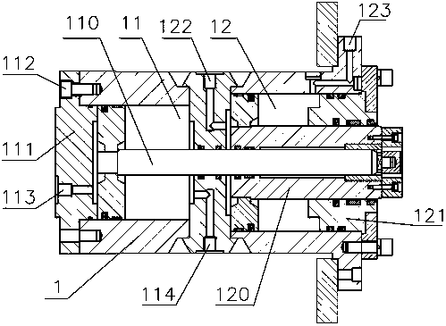
[0014] Such as figure 1 As shown, the present invention schematically shows a hydraulic cylinder.

[0015] The invention discloses a hydraulic cylinder, such as figure 1 As shown, including a hydraulic cylinder 1, a piston and a piston rod, the hydraulic cylinder 1 is set as two cavities, respectively a first cylinder 11 and a second cylinder 12, the piston includes a first piston and a second piston, and the piston The rod includes a first piston rod 110 and a second piston rod 120, the first piston and the first piston rod 110 are located in the first cylinder 11, the second piston and the second piston rod 120 are located in the second cylinder 12, and the second piston rod 110 is located...


PUM


Abstract

The invention provides a hydraulic oil cylinder. The hydraulic oil cylinder comprises a hydraulic cylinder body, a piston and a piston rod, wherein the hydraulic cylinder body is provided with two cavities, the two cavities are a first cylinder body and a second cylinder body respectively, the piston comprises a first piston and a second piston, the piston rod comprises a first piston rod and a second piston rod, and the first piston and the first piston rod are located in the first cylinder body, the second piston and the second piston rod are located in the second cylinder body, a through hole is formed in the axial direction of the second piston rod, the first piston rod penetrates through the through hole of the second piston rod, the first cylinder body and the second cylinder body are combined into a complete hydraulic cylinder body, different action requirements can be controlled respectively, the second piston rod of the second cylinder body realizes the working locking action,and the first piston rod of the first cylinder body realizes the stamping workpiece action. The hydraulic oil cylinder has the beneficial effect that the structure is compact, the assembly is simple,the maintenance are convenient, and the structural problem is solved for hydraulic intelligent control.

Description

technical field [0001] The invention relates to the technical field of oil cylinders, in particular to a hydraulic oil cylinder. Background technique [0002] The hydraulic cylinder is the working and executive element in the hydraulic system. People manufacture various hydraulic cylinders according to actual needs. Among them, the double-rod hydraulic cylinder has been widely used in many industries, but the two existing double-rod hydraulic cylinders The piston rod generally protrudes left and right, or cannot be controlled separately when protruding from the same end. In some special occasions, it is necessary to lock the workpiece first. This process requires slow pressure from the hydraulic cylinder. After locking, the workpiece is locked. Stamping, at this time, it needs to be stamped quickly, which requires separate control of the piston rod to meet the production requirements. Contents of the invention [0003] In order to overcome the problems existing in the pri...

Claims


Application Information

Patent Timeline
Patent Type & Authority Applications(China)
IPC IPC(8): F15B15/14
CPCF15B15/1404F15B15/1428
Inventor 钱亚平
Owner 常州华睿新能源汽车发展有限公司
Learn More