Method and device for measuring refractive index of rear spectrophotometric pupil laser differential confocal lens

A technology of differential confocal and measurement methods, which is applied in the directions of measuring devices, phase influence characteristic measurement, and material analysis, etc., which can solve problems such as system structure, complex assembly and adjustment process, and large errors, so as to reduce the impact and reduce measurement errors. Effect

Active Publication Date: 2019-01-11
BEIJING INSTITUTE OF TECHNOLOGYGY
View PDF7 Cites 8 Cited by
  • Summary
  • Abstract
  • Description
  • Claims
  • Application Information

AI Technical Summary

Problems solved by technology

However, two detectors must be used, and the position of the two detectors must be equal to the defocus amount. The system structure and the installation and adjustment process are more complica

Method used


Image

  • Method and device for measuring refractive index of rear spectrophotometric pupil laser differential confocal lens
  • Method and device for measuring refractive index of rear spectrophotometric pupil laser differential confocal lens
  • Method and device for measuring refractive index of rear spectrophotometric pupil laser differential confocal lens

Examples


Embodiment 1

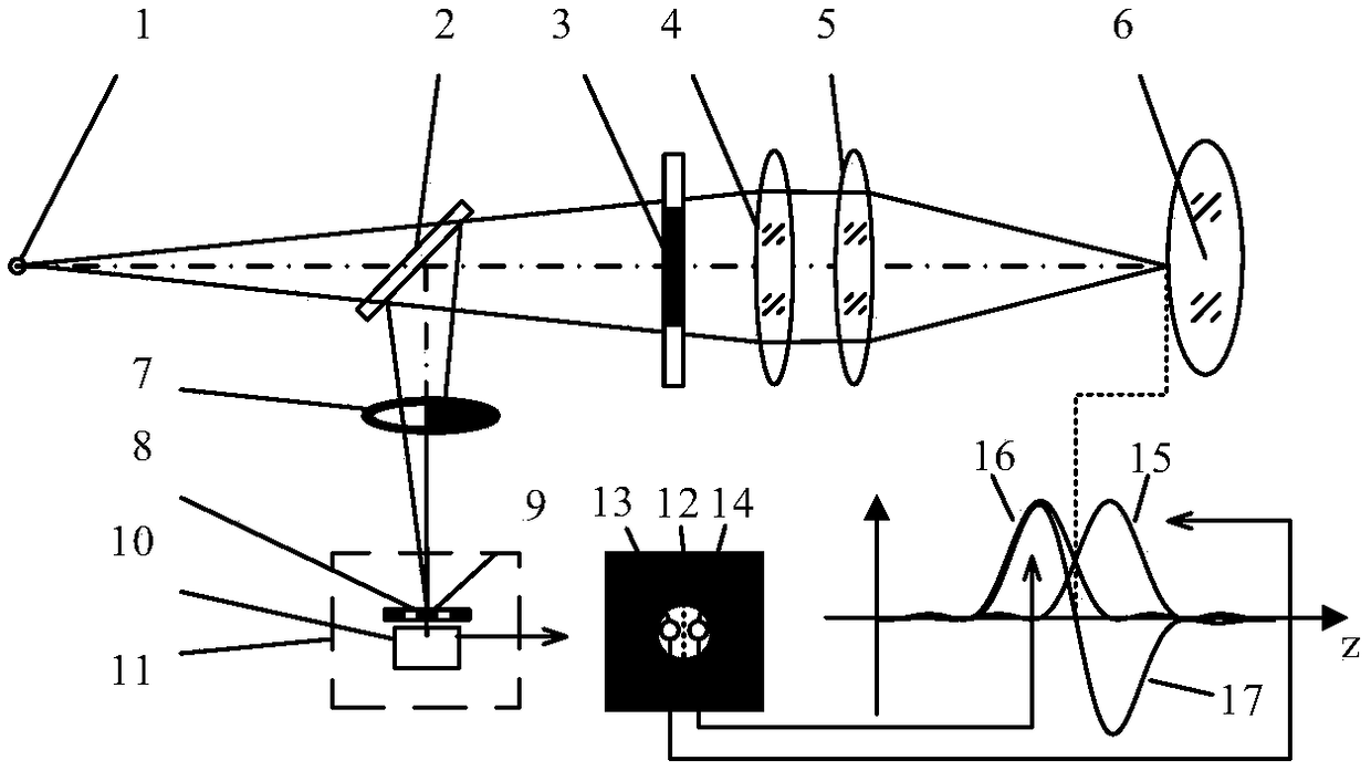
[0047] Such as Figure 4 As shown, the post-pupil laser differential confocal lens refractive index measurement device includes a laser 22, an optical fiber 23 and a point light source 1, which are sequentially placed in the beam splitter 2, collimating lens 4 and converging The lens 5 also includes a D-shaped rear pupil 7 placed in the reflection direction of the beam splitter 2 and a split-pupil differential confocal detection system 11 composed of a microscope objective lens 20 and a CCD 21; a main control computer 24 and a motor drive system 25 connected so that it drives the lens under test 6 to scan along the optical axis on the linear guide rail 26 .

[0048] When using the device to measure the refractive index of the lens, use the split-pupil differential confocal detection system 11 in the system to locate the vertex position of the front surface and the vertex position of the rear surface of the measured lens 6 with high precision, and then measure its refractive in...

Embodiment 2

[0059] The measurement steps in this embodiment are the same as in Embodiment 1, as Figure 5 Shown is the center measurement device diagram of the rear split-pupil laser differential confocal lens in this embodiment, Figure 4 The D-type rear pupil 7 in is replaced by the circular rear pupil 30 here.


PUM


Abstract

The invention relates to a method and device for measuring the refractive index of a rear spectrophotometric pupil laser differential confocal lens, and belongs to the technical field of optical precision measurement. According to the method and the device in the invention, half measurement beams are kept out by utilization of a rear pupil; front and rear surface vertexes of a measured lens are respectively fixed precisely by utilization of the absolute zero point of a differential confocal response curve; and the refractive index is obtained through ray tracing and a compensation model thereof. According to the method and the device in the invention, a rear spectrophotometric pupil laser differential confocal technology is used for high-precision detection of the refractive index of the lens for the first time; differential confocal focus-fixing and lens refractive index measurement can be realized only by one detector; a laser differential confocal technology and a ray tracing technology are organically fused; ray tracing and the compensation model thereof are established, so that influence among various focused surface parameters is eliminated; furthermore, the data near the absolute zero point is linearly fitted, so that quick trigger focusing is realized; the system structure and the installation and debugging process are greatly simplified; the problem that the focus-fixing precision is decreased possibly due to replacement of the measured lens is avoided; and the measurement speed and precision and the anti-scattering capability are greatly improved.

Description

technical field [0001] The invention relates to a method and a device for measuring the refractive index of a post-divided pupil laser differential confocal lens, which can be used for non-contact high-precision measurement of the lens refractive index and belongs to the technical field of optical precision measurement. Background technique [0002] Spherical lenses are one of the most important components in an optical system. The refractive index of a spherical lens is its basic parameter, which directly determines the performance parameters such as the focal length and the position of the main plane of the lens. Therefore, the measurement of the refractive index of a spherical lens has always been the most basic problem in optical measurement. At present, the main methods for measuring the refractive index of glass are: V prism method and right angle irradiation method. The measurement accuracy of these two methods is very high, but the lens material needs to be processe...

Claims


Application Information

Patent Timeline
IPC IPC(8): G01N21/41G01N21/01
CPCG01N21/01G01N21/41G01N21/4133
Inventor 赵维谦杨帅邱丽荣张培洁
Owner BEIJING INSTITUTE OF TECHNOLOGYGY
Why Eureka
Try Eureka