
Boundary test circuit, memory and boundary test method

A boundary test and boundary register technology, applied in the electrical field, can solve the problems of low test efficiency and poor flexibility, and achieve the effect of improving test flexibility and test efficiency

Pending Publication Date: 2019-01-11
CHANGXIN MEMORY TECH INC
View PDF7 Cites 2 Cited by
  • Summary
  • Abstract
  • Description
  • Claims
  • Application Information

AI Technical Summary

Problems solved by technology

[0007] The purpose of this disclosure is to provide a boundary test circuit, memory and boundary test method, and then at least to a certain extent overcome the technical problems of low test efficiency and poor flexibility caused by the limitations and defects of related technologies

Method used


Image

  • Boundary test circuit, memory and boundary test method
  • Boundary test circuit, memory and boundary test method
  • Boundary test circuit, memory and boundary test method

Examples


Embodiment Construction

[0052] Example embodiments will now be described more fully with reference to the accompanying drawings. However, the example embodiments can be implemented in various forms, and should not be construed as being limited to the embodiments set forth herein; on the contrary, these embodiments are provided so that the present invention will be comprehensive and complete, and fully convey the concept of the example embodiments To those skilled in the art. The same reference numerals in the figures represent the same or similar structures, and thus their detailed descriptions will be omitted.

[0053] Although relative terms such as "upper" and "lower" are used in this specification to describe the relative relationship between one component of an icon and another component, these terms are used in this specification only for convenience, for example, according to the drawings. The direction of the example described. It can be understood that if the device of the icon is turned over...


PUM


Abstract

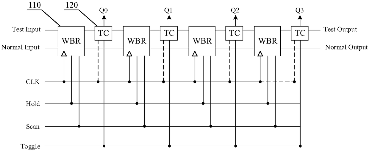
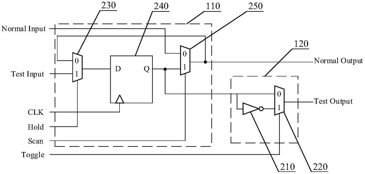
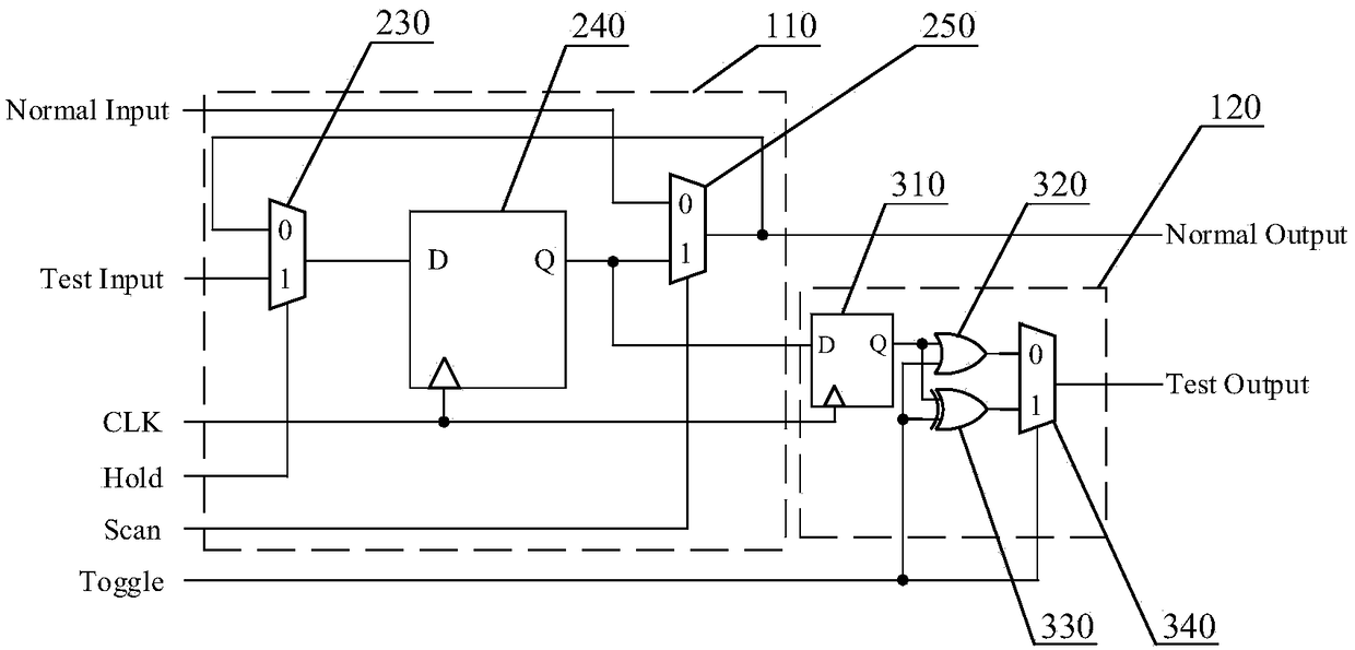
The invention relates to a boundary test circuit, a memory and a boundary test method. The boundary test circuit in an embodiment of the invention comprises a plurality of boundary register circuits.One end of each boundary register circuit receives an initial test signal, and the other end thereof transmits the initial test signal to a next boundary register circuit. The boundary test circuit also comprises a plurality of state control circuits, wherein an input terminal of each state control circuit receives an initial test signal stored in the boundary register circuit, a control terminalof the state control circuit receives a state control signal, and an output terminal of the state control circuit sends a real-time test signal to an integrated circuit to be tested; the real-time test signal is the signal with the same phase or opposite phase as the initial test signal. Boundary test circuits provided by embodiments of the present disclosure may improve test efficiency and test flexibility.

Description

Technical field [0001] The present disclosure relates to the field of electrical technology, in particular to a boundary test circuit, a memory and a boundary test method. Background technique [0002] In modern electronic application systems, with the emergence of large-scale integrated circuits, the manufacturing process of printed circuit boards is developing towards small, micro, and thin. The number of pins and pin density of components continue to increase. The use of multimeters and oscilloscopes to test chips The traditional "probe" test method can no longer meet the requirements. [0003] In this context, boundary scan testing came into being. The boundary scan test is implemented by attaching a boundary scan cell (Boundary Scan Cell, BSC for short) and some additional test control logic to each I / O pin of the chip. The BSC is mainly composed of registers. Each I / O pin of the chip has a BSC, and each BSC has two data channels: one is a test data channel, including test d...

Claims


Application Information

Patent Timeline
IPC IPC(8): G11C29/56
CPCG11C29/56
Inventor 杨正杰
Owner CHANGXIN MEMORY TECH INC
Learn More