Method for the automated electronic control of a braking system and electronically controllable braking system in a utility vehicle
What is Al technical title?
Al technical title is built by PatSnap Al team. It summarizes the technical point description of the patent document.
A braking system and commercial vehicle technology, applied in the direction of braking system interaction, braking safety system, braking control system, etc., can solve problems such as inattention, and achieve the effect of improving reliability
Active Publication Date: 2019-01-11
WABCO EURO BVBA SPRL
View PDF27 Cites 5 Cited by
Summary
Abstract
Description
Claims
Application Information
AI Technical Summary
This helps you quickly interpret patents by identifying the three key elements:
Problems solved by technology
Method used
Benefits of technology
Problems solved by technology
However, this is usually not the case in an automated vehicle, especially when there is no driver in or in the driver's seat or the driver is distracted or busy with other things
Method used
Image
Click on the blue label to locate the original text in one second.
Reading with bidirectional positioning of images and text.
Examples
Embodiment Construction
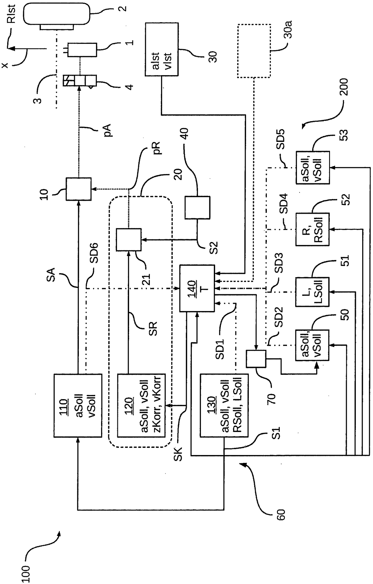
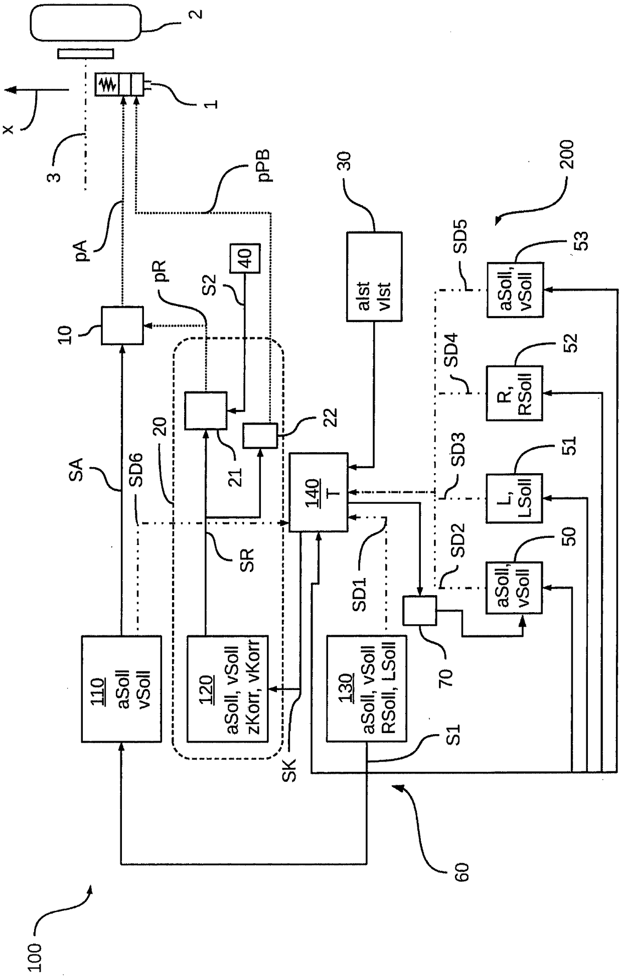
[0062] in accordance with figure 1 In an embodiment of the present invention, a section from brake system 100 of vehicle 200 is shown as a block diagram. Braking system 100 thus has a first control device 110 , a second control device 120 and a monitoring device 140 . Braking system 100 is designed to decelerate vehicle 200 via wheel brakes 1 , which are each assigned to wheels 2 of an axle 3 and optionally upstreamed by electronically controllable ABS brake valves 4 . For simplicity, in accordance with figure 1 Only the right front wheel 2 of the front axle 3 of the vehicle 200 is shown in the embodiment of the example. The other wheels can be implemented in a corresponding manner with or without ABS brake valve 4 .
[0063] Furthermore, a control device 130 is shown, which is assigned to a control system of the vehicle 200 , which is designed to be automatically controlled, for example, as a function of the planned vehicle movement F, in particular taking into account the...
PUM
Abstract
The invention relates to a method for the automated electronic control of a braking system (100) in a vehicle (200), having at least the following steps: - reading a request signal (S1) for the automated electronic triggering of actuators (1, 50, 52, 53) in the vehicle (200), wherein at least one of the actuators (1, 50, 52, 53) has an influence on an actual longitudinal dynamic of the vehicle (200), and requests (aSoll, vSoll, RSoll) to establish an automatically requested target longitudinal dynamic of the vehicle which are to be implemented by the actuators (1, 50, 52, 53) are transmitted via the request signal (S1); - plausibility-checking the request signal (S1) to determine whether the requests (aSoll, vSoll, RSoll) to establish the automatically requested target longitudinal dynamicof the vehicle are being or can be fully and correctly implemented by the actuators (1, 50, 52, 53); - defining a correction deceleration (zKorr) and / or a correction speed (vKorr) if at least one ofthe requests (aSoll, vSoll, RSoll) is not or cannot be fully and correctly implemented, to specify corrective braking, the correction deceleration (zKorr) and / or the correction speed (vKorr) being determined depending on the request (aSoll, vSoll, RSoll) which is not or cannot be fully and correctly implemented; - requesting the corrective braking of the vehicle (200) depending on the correction deceleration (zKorr) and / or on the correction speed (vKorr) to put the vehicle (200) into a safe state.
Description
technical field [0001] The invention relates to a method for automated electronic control of a brake system and to an electronically controllable brake system in a commercial vehicle, in particular in an automated controllable commercial vehicle. Background technique [0002] In vehicles, in particular commercial vehicles, with a pneumatic brake system, in particular designed as an electronic service brake system (EBS), an electronically controlled valve, such as a relay valve, can be actuated by the control unit (ECU) for regulating the brake pressure. or the axle modulator, and then the electronically controlled valve pneumatically regulates the brake pressure to the brake cylinders of the service brakes of the braking system as a function of the requested target acceleration of the vehicle. Depending on the driver's actuation of the brake force regulator or brake value transmitter via the brake pedal, the control of the brake pressure is superimposed on the electronic con...
Claims
Application Information
Patent Timeline
Application Date:The date an application was filed.
Publication Date:The date a patent or application was officially published.
First Publication Date:The earliest publication date of a patent with the same application number.
Issue Date:Publication date of the patent grant document.
PCT Entry Date:The Entry date of PCT National Phase.
Estimated Expiry Date:The statutory expiry date of a patent right according to the Patent Law, and it is the longest term of protection that the patent right can achieve without the termination of the patent right due to other reasons(Term extension factor has been taken into account ).
Invalid Date:Actual expiry date is based on effective date or publication date of legal transaction data of invalid patent.