
Outlet valve for a flush tank and flush tank having an outlet valve

A technique for drain valves and flush tanks, applied in the field of sanitary flush tanks, which can solve problems such as difficulty in dismantling drain valves, and achieve the effect of improving and simplifying operations

Active Publication Date: 2019-01-11
VIEGA TECH GMBH & CO KG
View PDF5 Cites 0 Cited by
  • Summary
  • Abstract
  • Description
  • Claims
  • Application Information

AI Technical Summary

Problems solved by technology

As a result, installers often have to master difficult maneuvers when removing and installing drain valves

Method used


Image

  • Outlet valve for a flush tank and flush tank having an outlet valve
  • Outlet valve for a flush tank and flush tank having an outlet valve
  • Outlet valve for a flush tank and flush tank having an outlet valve

Examples


Embodiment Construction

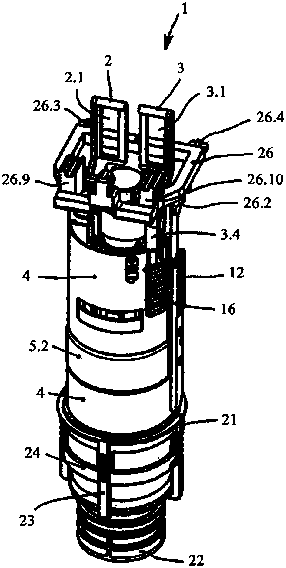
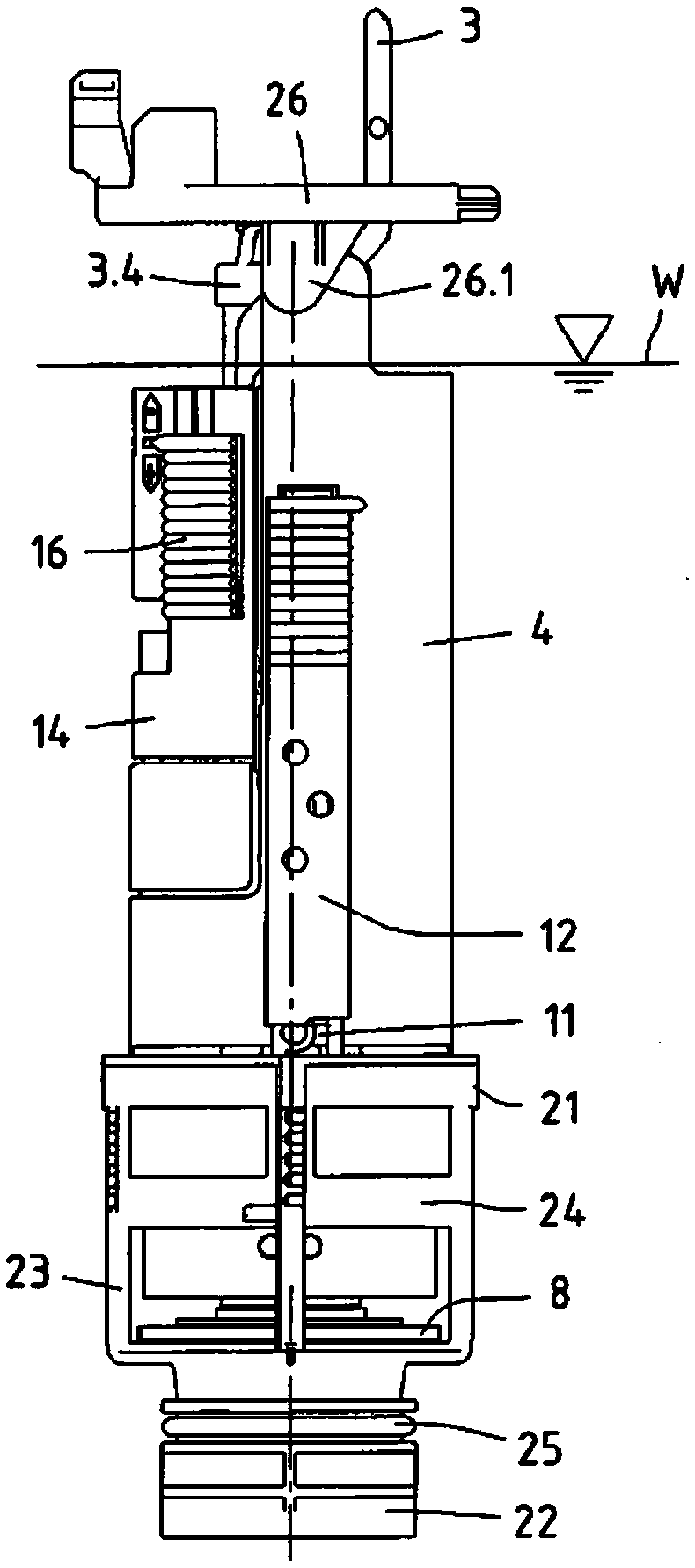
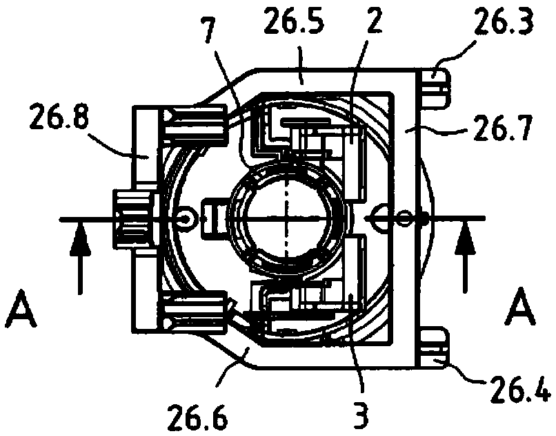
[0026] The figures of the figures show a drain valve 1 which can be installed in a sanitary cistern, in particular in a concealed cistern. The drain valve 1 is preferably designed as a dual-displacement drain valve, ie a larger flush volume for so-called full flushes or a smaller flush water volume for so-called partial flushes can be selectively delivered by means of the drain valve. For operating the drain valve 1 , an operating device (not shown) is arranged in the upper region of the tank. The operating device has two operating elements that can be controlled independently of one another. By way of example, the operating elements are implemented as movably mounted pushbuttons, wherein each pushbutton is assigned a lifting mechanism (not shown). The respective lifting mechanism is coupled to one of the two pull tabs 2, 3 of the drain valve 1, which has at its upper end an elongated lug 2.1, 3.1 in which the lifting mechanism engages.

[0027] The drain valve 1 has a subst...


PUM


Abstract

The invention relates to an outlet valve (1) for a sanitary flush tank (30), in particular a flush-mounted flush tank, comprising a valve housing (4) and a valve body (7), which is guided in the valvehousing and is designed as an overflow tube and has a seal (8) associated with a valve seat (9), wherein the valve body (7) is provided with at least one pulling tab (2, 3) for lifting the valve body(7) and with a buoyant body (10). In order to be able to install such an outlet valve more easily in a flush tank, in particular a flush-mounted flush tank, and to be able to remove such an outlet valve from the flush tank more easily in case of maintenance or repair, the valve housing (4) according to the invention is provided with a spacer (26) at the upper end of the valve housing for orienting and fastening the outlet valve (1) in the flush tank (30), wherein the pulling tab (2) is pivotably connected to the valve body (7) and the spacer (26) has an abutment (26.9) associated with the pulling tab (2), which abutment acts as a pivot point for the pulling tab (2) such that the pulling tab (2) can be moved from an upright position to a folded-over position and the valve body (7) connected to the pulling tab (2) is lifted with respect to the valve seat (9) in the folded-over position of the pulling tab (2).

Description

technical field [0001] The invention relates to a drain valve for sanitary flushing tanks, in particular for concealed flushing tanks, having a valve housing and a valve body guided in the valve housing and formed as an overflow pipe, the valve body has a corresponding valve seat A sealing element, wherein the valve body is provided with at least one pulling piece for raising the valve body and a floating body. Furthermore, the invention relates to a sanitary flushing tank, preferably in the form of a concealed flushing tank, with a rear wall, a front wall and a drain valve, wherein an access opening for installing and removing the drain valve is formed in the upper section of the front wall . Background technique [0002] Drain valves of the above-mentioned type have been known for a long time in various designs. In order to operate the drain valve reliably, it must be oriented and fixed substantially vertically in the flush tank. To secure the drain valve of a conventio...

Claims


Application Information

Patent Timeline
Patent Type & Authority Applications(China)
IPC IPC(8): E03D1/14E03D1/34
CPCE03D1/144E03D1/35
Inventor 克劳斯·阿伦斯弗兰克·富尔戈尼帕特里克·迪特尔曼
Owner VIEGA TECH GMBH & CO KG
Learn More